Precautions
3.1 Precautions
Power Supply Input Polarity and Maximum Voltage
Always ensure that the polarity and voltage of the external power connected to VCC power input connector J1, J2, and/or VDD power input connector J6 are correct. Overvoltage or
Inserting or Removing EVM Boards
Do not insert or remove EVM boards with power appliedÐdamage to the EVM board, the platform, or both may result.
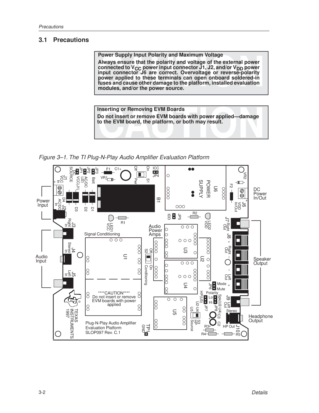
Figure 3±1. The TI Plug-N-Play Audio Amplifier Evaluation Platform
Power Input
J1 VCC In + | VCC(J1) DC SOURCE |
D4 J2 AC/DC In | D3 |
J3 Right In | |
JP1 |
| JP2 |
| JP3 |
|
| F1 | C1+ |
| Off | |||||||||
|
|
|
|
| |||||||||||||||
|
|
|
|
|
|
|
|
|
|
|
|
|
| ||||||
|
|
|
|
|
|
|
|
|
|
|
|
|
| ||||||
(J2) | AC/DC | Batt |
|
| VR1 |
|
|
|
|
|
|
|
|
| |||||
|
|
|
|
|
|
|
|
| Pwr | ||||||||||
|
|
|
|
|
|
|
|
|
|
|
| ||||||||
|
|
|
|
|
|
|
|
|
|
|
| ||||||||
|
|
|
|
|
|
|
|
|
|
|
|
|
|
|
| ||||
|
|
|
|
|
|
|
|
|
|
|
|
|
|
|
|
|
|
|
|
|
|
|
|
|
|
|
|
|
|
|
|
|
|
|
|
|
|
|
|
|
|
|
|
|
|
|
|
|
|
|
|
|
|
|
|
|
|
|
|
|
|
|
|
|
|
|
|
|
|
|
|
|
|
|
|
|
|
|
|
|
|
|
|
|
|
|
|
|
|
|
|
|
|
|
|
|
|
|
|
|
|
|
|
|
|
|
|
|
|
|
|
|
|
|
|
|
|
|
|
|
|
|
|
|
|
|
|
|
|
|
|
|
|
|
|
|
|
| |
| D2 | D1 |
|
|
|
|
|
|
|
|
|
|
|
|
|
| |||
|
|
|
|
|
|
|
|
|
|
|
|
|
|
| |||||
|
|
|
|
|
|
|
|
|
|
|
|
|
|
|
|
|
|
|
|
|
|
|
|
|
|
|
|
|
|
|
|
|
|
|
|
|
|
|
|
|
|
|
|
|
|
|
|
|
| LED1 VCC |
|
|
| R1 |
|
|
| ||
|
|
|
|
|
|
|
|
|
|
|
|
|
|
|
|
| |||
On | ICC | ||
| |||
|
|
|
|
S1 | JP4 |
| |
|
|
| |
B1 |
|
IDD | JP5 |
Audio |
|
Power |
|
SUPPLY | POWER |
| VR2 |
U6 | F2 | ||
|
|
| DC |
|
|
| Power |
|
|
| In/Out |
|
|
| + |
R2 |
|
| J6 VDD In/Out |
|
|
| |
| LED2 VDD |
| J7 |
|
| Right Out |
Audio Input
|
| J4 Stereo In | ||
|
|
|
| |
|
|
|
|
|
|
|
|
|
|
|
|
|
| |
|
| J5 Left In | ||
|
|
|
|
|
|
|
|
|
|
|
|
|
|
|
|
|
|
|
|
TEXAS INSTRUMENTS 1997
Signal Conditioning |
U1 |
****CAUTION****
Do not insert or remove EVM boards with power applied
SLOP097 Rev. C.1
| Amps |
|
S2 | Off | U3 |
Conditioning | On | U4 |
|
| U5 |
TP1 GND |
| |
|
|
|
|
| J8 + |
|
| U2 |
|
| Right Out |
| |
|
|
|
| ± |
| |
|
|
|
|
| ± |
|
|
|
|
| Left Out |
| |
| JP6 | Mode | + |
| ||
| Mute |
| ||||
JP7 HP(U5) |
|
| ||||
JP8 |
|
|
| |||
| Polarity |
| J9 |
| ||
| Lo |
|
|
|
|
|
| Hi |
|
| Left Out |
| |
|
|
|
|
| ||
|
|
|
|
| Stereo | |
S3 HP Source | + |
| C3 |
|
| J10 |
R3 |
| C2 | HP Out | |||
| + |
|
|
|
|
|
| R4 |
|
|
|
| R5 |
Speaker
Output
Headphone Output
Details |