Quick Start List for
2.3 Quick Start List for Stand-Alone
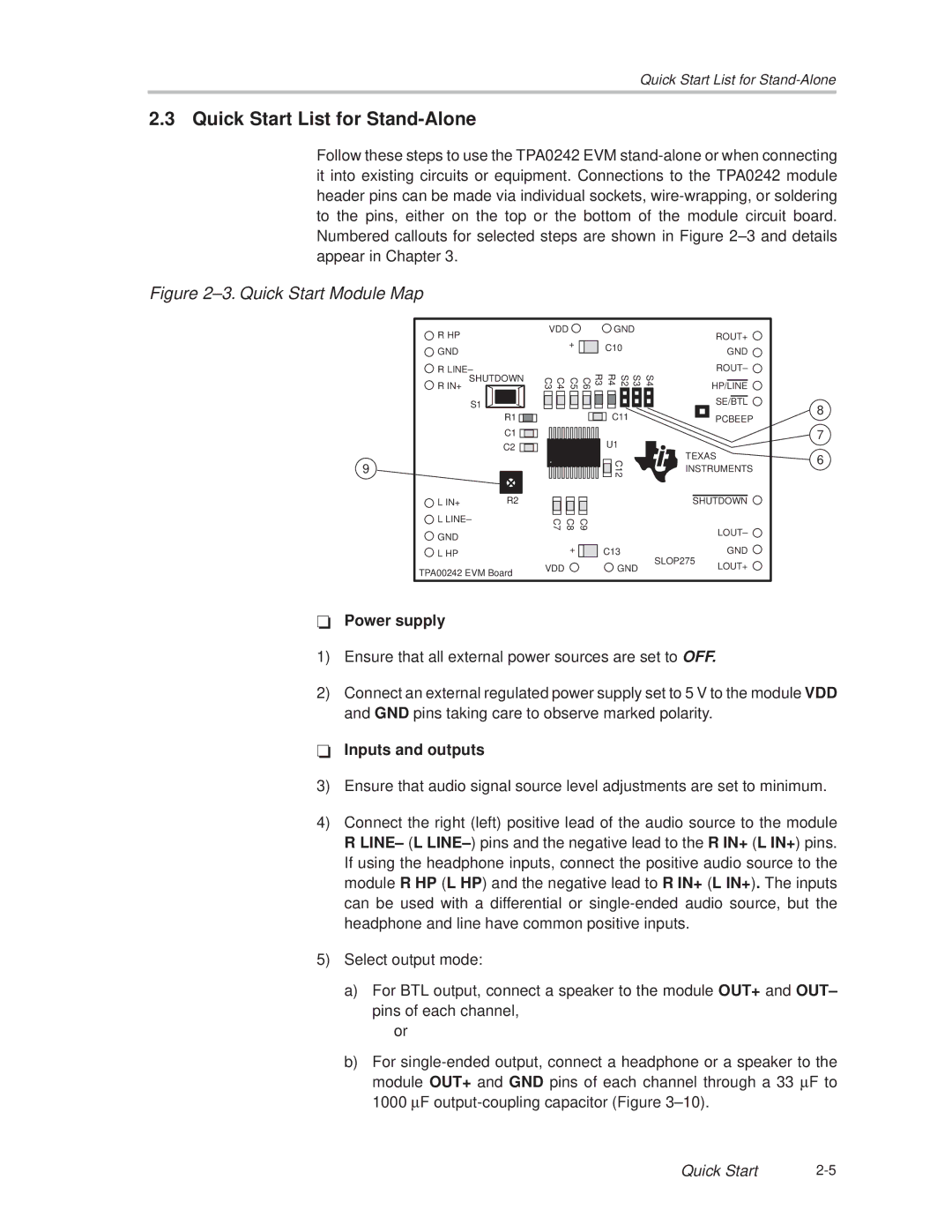
Follow these steps to use the TPA0242 EVM
Figure 2±3. Quick Start Module Map
9
R HP |
GND |
R LINE± |
SHUTDOWN |
R IN+ |
S1 |
R1 ![]()
![]()
C1 ![]()
![]()
![]()
![]()
C2 ![]()
![]()
![]()
|
|
L IN+ | R2 |
| VDD |
|
|
|
|
|
|
| GND |
|
| ||||||
|
|
|
| + |
|
|
|
|
| C10 |
|
|
|
| |||
|
|
|
|
|
|
|
|
|
|
|
|
| |||||
|
|
|
|
|
|
|
|
|
|
|
|
|
|
|
| ||
C3 | C4 | C5 | C6 |
| R3 |
| R4 |
| S2 |
| S3 |
| S4 | ||||
|
|
|
|
|
|
|
|
|
|
|
|
|
|
|
|
|
|
|
|
|
|
|
|
|
|
|
|
|
|
|
|
|
|
|
|
|
|
|
|
|
|
|
|
|
|
|
|
|
|
|
|
|
|
|
|
|
|
|
|
|
|
|
|
| C11 |
|
|
|
| ||
|
|
|
|
|
|
|
|
|
|
|
|
|
|
| |||
|
|
|
|
|
|
|
|
|
|
| U1 |
|
|
|
| ||
|
|
|
|
|
|
|
|
|
|
|
|
|
|
| |||
|
|
|
|
|
|
|
|
|
|
|
|
|
|
| |||
|
|
|
|
|
|
|
|
|
|
|
| C12 |
|
|
|
| |
|
|
|
|
|
|
|
|
|
|
|
|
|
|
|
| ||
|
|
|
|
|
|
|
|
|
|
|
|
|
|
|
| ||
ROUT+
GND
ROUT± ![]()
HP/LINE
SE/BTL
PCBEEP
TEXAS INSTRUMENTS
SHUTDOWN
8
7
6
![]() L LINE±
L LINE±
![]() GND
GND
![]() L HP
L HP
TPA00242 EVM Board
C7 | C8 | C9 |
| LOUT± |
|
|
|
| |
| + | C13 | SLOP275 | GND |
VDD |
| GND | LOUT+ | |
|
|
-Power supply
1)Ensure that all external power sources are set to OFF.
2)Connect an external regulated power supply set to 5 V to the module VDD and GND pins taking care to observe marked polarity.
-Inputs and outputs
3)Ensure that audio signal source level adjustments are set to minimum.
4)Connect the right (left) positive lead of the audio source to the module R LINE± (L LINE±) pins and the negative lead to the R IN+ (L IN+) pins. If using the headphone inputs, connect the positive audio source to the module R HP (L HP) and the negative lead to R IN+ (L IN+). The inputs can be used with a differential or
5)Select output mode:
a)For BTL output, connect a speaker to the module OUT+ and OUT± pins of each channel,
or
b)For
Quick Start |
