Using The TPA0242 EVM With the
3.3.2TPA0242 Module Jumper Settings and Switches
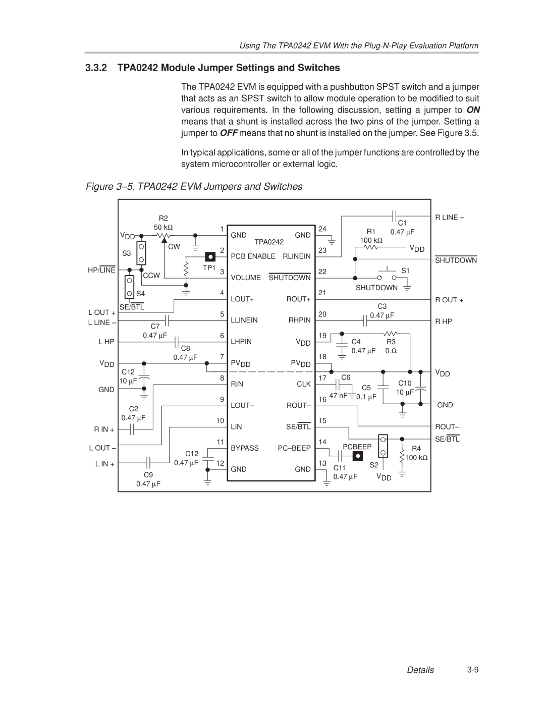
The TPA0242 EVM is equipped with a pushbutton SPST switch and a jumper that acts as an SPST switch to allow module operation to be modified to suit various requirements. In the following discussion, setting a jumper to ON means that a shunt is installed across the two pins of the jumper. Setting a jumper to OFF means that no shunt is installed on the jumper. See Figure 3.5.
In typical applications, some or all of the jumper functions are controlled by the system microcontroller or external logic.
Figure 3±5. TPA0242 EVM Jumpers and Switches
| R2 |
|
|
|
|
|
| C1 |
| 50 kΩ | 1 |
| 24 |
|
|
| |
|
|
| R1 | 0.47 µF | ||||
| VDD | GND |
| GND |
| |||
|
|
| 100 kΩ |
| ||||
| CW | TPA0242 |
| VDD | ||||
| 2 |
| 23 |
|
|
| ||
| S3 | PCB ENABLE | RLINEIN |
|
|
|
| |
|
|
|
|
|
| |||
HP/LINE | CCW | TP1 3 |
| 22 |
|
|
| S1 |
| VOLUME | SHUTDOWN |
|
|
|
| ||
|
|
|
|
|
| |||
| S4 | 4 |
| 21 |
| SHUTDOWN | ||
|
|
|
|
|
| |||
|
| LOUT+ |
| ROUT+ |
|
| C3 |
|
L OUT + | SE/BTL | 5 |
| 20 |
|
|
| |
|
|
| 0.47 µF |
| ||||
L LINE ± | C7 | LLINEIN |
| RHPIN |
|
|
|
|
|
|
|
|
|
|
| ||
|
|
|
|
|
|
|
| |
| 0.47 µF | 6 |
| 19 |
|
|
|
|
L HP | C8 | LHPIN |
| VDD |
| C4 | R3 |
|
|
|
|
|
| 0.47 µF | 0 Ω | ||
VDD | 0.47 µF | 7 |
| 18 |
|
|
|
|
C12 | PVDD |
| PVDD |
|
|
|
| |
| 8 |
| 17 | C6 |
|
|
| |
| 10 µF |
|
|
| C10 | |||
| RIN |
| CLK |
| C5 |
| ||
GND |
|
|
|
| ||||
|
|
|
| 47 nF |
| 10 µF | ||
| 9 |
| 16 | 0.1 µF | ||||
|
|
|
| |||||
| C2 | LOUT± |
| ROUT± |
|
|
|
|
|
|
|
|
|
|
|
| |
| 0.47 µF | 10 |
| 15 |
|
|
|
|
|
|
|
|
|
|
| ||
R IN + |
| LIN |
| SE/BTL |
|
|
|
|
|
|
|
|
|
|
|
| |
L OUT ± |
| 11 |
| 14 | PCBEEP |
|
| |
C12 | BYPASS |
| PC±BEEP |
| R4 | |||
|
|
|
|
|
|
| 100 kΩ | |
L IN + | 0.47 µF | 12 |
| 13 |
| S2 | ||
| C11 |
| ||||||
| C9 | GND |
| GND |
| VDD |
| |
|
|
|
| 0.47 µF |
| |||
| 0.47 µF |
|
|
|
|
|
|
|
R LINE ±
SHUTDOWN
R OUT +
R HP
VDD
GND
ROUT±
SE/BTL
Details
