Quick Start List for Platform
-Evaluation module preparations
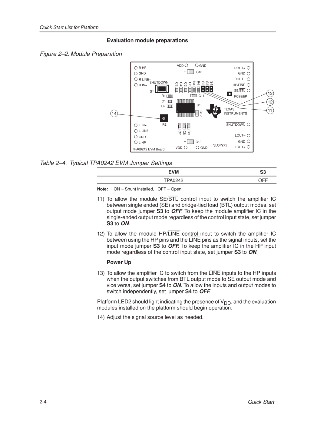
Figure 2±2. Module Preparation
14
R HP |
GND |
R LINE± |
SHUTDOWN |
R IN+ |
S1 |
R1 ![]()
![]()
C1 ![]()
![]()
![]()
![]()
C2 ![]()
![]()
![]()
|
|
L IN+ | R2 |
| VDD |
|
|
|
|
|
| GND |
|
| ||||||
|
|
|
| + |
|
|
|
| C10 |
|
|
|
| |||
|
|
|
|
|
|
|
|
|
|
|
| |||||
|
|
|
|
|
|
|
|
| R4 |
|
|
|
|
|
| |
C3 | C4 | C5 | C6 |
| R3 |
|
| S2 |
| S3 |
| S4 | ||||
|
|
|
|
|
|
|
|
|
|
|
|
|
|
|
|
|
|
|
|
|
|
|
|
|
|
|
|
|
|
|
|
|
|
|
|
|
|
|
|
|
|
|
|
|
|
|
|
|
|
|
|
|
|
|
|
|
|
|
|
| C11 |
|
|
|
| ||
|
|
|
|
|
|
|
|
|
| U1 |
|
|
|
| ||
|
|
|
|
|
|
|
|
|
|
|
|
|
| |||
|
|
|
|
|
|
|
|
|
|
|
|
|
| |||
|
|
|
|
|
|
|
|
|
|
| C12 |
|
|
|
| |
|
|
|
|
|
|
|
|
|
|
|
|
|
|
| ||
|
|
|
|
|
|
|
|
|
|
|
|
|
|
| ||
ROUT+
GND
ROUT± ![]()
HP/LINE
SE/BTL
PCBEEP
TEXAS INSTRUMENTS
SHUTDOWN
13
12
11
![]() L LINE±
L LINE±
![]() GND
GND
![]() L HP
L HP
TPA00242 EVM Board
C7 | C8 | C9 |
| LOUT± |
|
|
|
| |
| + | C13 | SLOP275 | GND |
VDD |
| GND | LOUT+ | |
|
|
Table 2±4. Typical TPA0242 EVM Jumper Settings
EVM | S3 |
TPA0242 | OFF |
Note: ON = Shunt installed, OFF = Open
11)To allow the module SE/BTL control input to switch the amplifier IC between single ended (SE) and
12)To allow the module HP/LINE control input to switch the amplifier IC between using the HP pins and the LINE pins as the signal inputs, set the input mode jumper S3 to OFF. To keep the amplifier IC in the HP input mode regardless of the control input state, set jumper S3 to ON.
-Power Up
13)To allow the amplifier IC to switch from the LINE inputs to the HP inputs when the output switches from BTL output mode to SE output mode and vice versa, set jumper S4 to ON. To allow the inputs and output modes to switch independently, set jumper S4 to OFF.
Platform LED2 should light indicating the presence of VDD, and the evaluation modules installed on the platform should begin operation.
14) Adjust the signal source level as needed.
Quick Start |