OH8FA119D60B
OH6FA072D48B
OH6FA072DV4B
OH6FA072D48R
CONTENTS
Fuel
Configuration
Model Number Digit
Heat Exchanger Identifier
CAUTION DO NOT ATTEMPT TO START THE BURNER WHEN
I. SAFETY SECTION
WARNING AND CAUTIONS
1.Excess oil has accumulated
Page
A. CODES AND CLEARANCES
a. Combustible material
b.Non-combustiblematerial
FROM
TYPE OF
MODEL NO.1
TOP
A. CHIMNEY
1. PREVENTION OF CHIMNEY CONDENSING
3. PROPER VENT CONNECTOR PIPE/CHIMNEY CONNECTION
2. PROPER CHIMNEY HEIGHT
7. NO INTERCONNECTED CHIMNEY FLUES
6. TIGHT CLEAN-OUTDOORS AND CONNECTIONS
5. TIGHT JOINTS
8. FLUE PIPE CLEARANCES, SIZING AND TYPE
A.Equal the required clearance with no protection
B. VENTING
ROTATION OF FRONT FLUE ELBOW
Airflow Requirements and Sizing of Duct Work
C. DRAFT REGULATORS
D. DUCT WORK/AIR CONDITIONING
Note Do not use with Direct Vent application
Page
Page
7.The supply and return air ducts, or flexible joints, should be carefully secured and sealed to the appliance housing to prevent air leakage from, or into, the duct system. For best performance, insulate the outside surfaces of the ducts to reduce heat loss from, or heat gain to, the ducts
1.HEATING CFM HEAT OUTPUT OF FURNACE BTUH
E. Air Filter Mounted External to Furnace
1.1 X TR TEMPERATURE RISE, F = HEATINGCFM
Connect the return air plenum to the filter rack and slide the filter into place. Dimensions for adapting the return air plenum to the filter rack are provided See Fig. 10a & 10b
Filter Type
F. LIMIT POSITION AND LOCATION
Maximum
Air Velocity
G. BURNER INSTALLATION
+ INSULATOR S = SLEEVE OR N = NONE
H. BURNER SPECIFICATIONS AND APPLICATIONS
DO NOT CHANGE POSITION OF THE CHAMBER
EQUIVALENT HEAT
OIL NOZZLE CAPACITY CHART
NOZZLE SIZE
EFFECTIVE HEATING
CAPACITY
MOUNTING THE 2-STAGERIELLO BURNER
2 STAGE FIRING RATES
FIRING
I. OIL TANK AND PIPING
J. OIL FILTER
K. ELECTRICAL WIRIING
Model
Assembly
Maximum
115 VAC
Thermostat Anticipator Setting
Preferred method of adjustment
L. Blower Motor Speed Selection
Furnace Motor Current
Heating Speed Set-ups
OH6FA072DV4
Draw Amps/ / Watts vs
Furnace Motor Current
Heating Speed Set-ups
OH8FA119DV5
Draw Amps / Watts vs
Heating Speed Set-ups 2 - Stage OH6FX072DV4
SWITCH
SETTINGS
LOW CAPACITY
Furnace Motor Current Draw Amps / Watts vs
Figure 18-3 Cooling blower motor speed chart
Cooling Speed Set-ups OH6F*072DV4
External Static Pressure in W.C
Furnace Motor Current
Figure 18-3A Cooling blower motor speed chart
Cooling Speed Set-ups OH8FA119DV5
Draw Amps/Watts vs
OH6FA072D48
Med-Low= Blue Med-High= Yellow High = Black
OH8FA119D60
Speed vs. color code for PSC Motor Low = Red
M. BLOWER CONTROLLER INFORMATION FOR PSC MOTOR
TERMINAL DEFINITIONS & FIELD WIRING
A. Inputs
B. Outputs
C. Operating Modes
Heat Mode
ECM & PSC TROUBLE SHOOTING
DIAGNOSTIC FEATURES
For Your Safety Read Before Operating
N.STARTUP PROCEDURES
Operating Instructions
i.STOP! Read the safety information above
2. Adjustment of Burner Combustion
To Turn Off Oil to Appliance
COMBUSTION HEAD SETTING FOR 2-STAGERIELLO BURNER
TURN TO THE LEFT SIGN
AIR DAMPER ADJUSTMENT
TURN TO THE RIGHT SIGN +
1st STAGE ADJUSTMENT
2nd STAGE ADJUSTMENT
3. Adjustment Of Heat Input Rate
Notice Minimum return air temperature is 55F
4. Setting Supply Air Temperature Rise
5. Checkout Procedure
CAUTION DO NOT ATTEMPT TO MAKE REPAIRS YOURSELF
III. USERS INFORMATION SECTION
C. INSPECTION AREAS
CAUTION DO NOT ATTEMPT TO START THE BURNER WHEN
E. FILTER CLEANING AND LOCATION
D. STARTING THE BURNER
IV. INSTALLERS INSTRUCTIONS TO USER
SAFETY DURING SERVICING AND INSPECTION
V. DEALER MAINTENANCE
A.GENERAL INSPECTION
C. HEAT EXCHANGER CLEANING INSTRUCTIONS
B. HEAT EXCHANGER
Figure 24 Heat Exchanger Clean-Outs
Vacuum Hose Length OH6 8FT OH8 8FT
E. SUPPLY/RETURN AIR BLOWER
Filter maintenance procedure
D. ELECTRICAL SYSTEM
F. SUPPLY/RETURN AIR FILTER
Filter replacement
G. EXTENDED APPLIANCE SHUTDOWN
ON STARTUP
Beckett Burner
VII. TROUBLESHOOTING
PERSONNEL, AND NOT BY THE FURNACE OWNER
B. CAD CELL CHECKOUT PROCEDURE
A. DIAGNOSTICS
Diagnostic Features
Number of flashes
Page
VIII. Sequence of Operations Flow Chart
Page
IX. Trouble Shooting Flow Chart
Page
Page
Page
Page
SYSTEM
CUSTOMER
HEATING
COM BUSTION
Appendix - A Replacement Parts
Replacement Parts for OH6FA072D
Replacement Parts for OH8FA119D
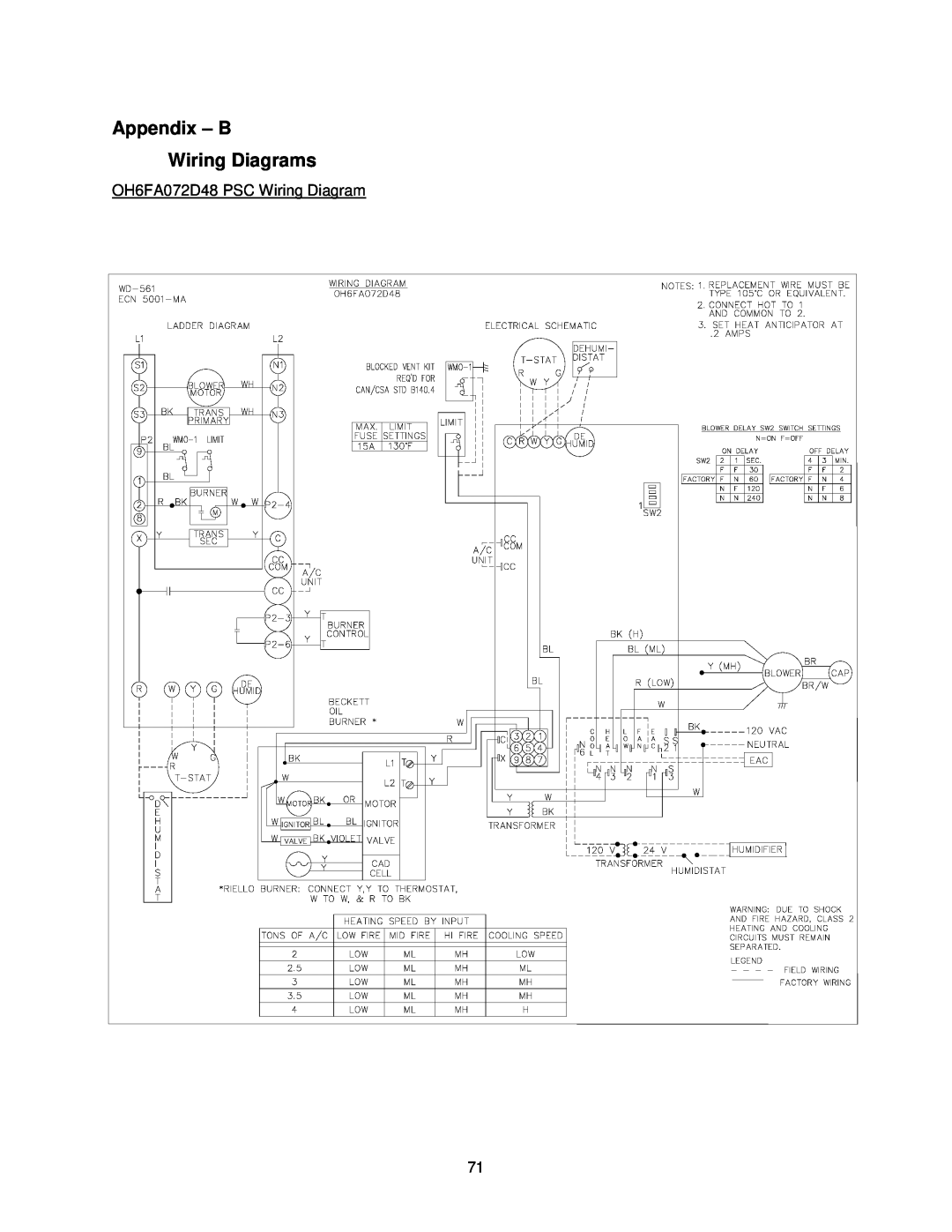
Appendix - B Wiring Diagrams
OH6FA072D48 PSC Wiring Diagram
OH6FA072DV4 ECM Wiring Diagram
OH6FX072DV4 ECM 2-StageWiring Diagram
OH8FA1119D60 PSC Wiring Diagram
OH8FA1119DV5 ECM Wiring Diagram