Precautions

2.1 Precautions

Power Supply Input Polarity and Maximum Voltage

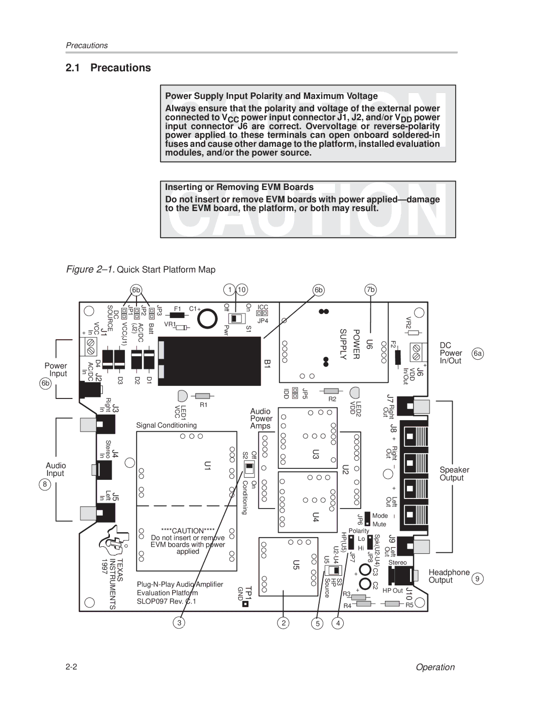
Always ensure that the polarity and voltage of the external power connected to VCC power input connector J1, J2, and/or VDD power input connector J6 are correct. Overvoltage or reverse-polarity power applied to these terminals can open onboard soldered-in fuses and cause other damage to the platform, installed evaluation modules, and/or the power source.

Inserting or Removing EVM Boards

Do not insert or remove EVM boards with power appliedÐdamage to the EVM board, the platform, or both may result.

Figure 2±1. Quick Start Platform Map

6b

1

10

6b

7b

Power Input

6b

In +

VCC(J1) DC SOURCE J1 VCC

AC/DC In

D4 J2

D3

JP1


JP2


JP3


F1


C1+

Off


(J2)

AC/DC

Batt


VR1


Pwr


D2

D1


On

ICC


S1

JP4


B1


IDD

JP5

SUPPLY

POWER


VR2

U6

F2

DC


Power 6a


In/Out


+


J6 VDD In/Out

Audio Input

8


Right In

J3


Stereo In

J4


Left In

J5


TEXAS INSTRUMENTS 1997

LED1 VCC

R1


Signal Conditioning


U1

****CAUTION****

Do not insert or remove EVM boards with power applied

Plug-N-Play Audio Amplifier

Evaluation Platform

SLOP097 Rev. C.1

3


Audio


Power


Amps


S2

Off

U3

Conditioning

On

U4

U5

TP1

GND

2 5

R2


LED2 VDD


J7


Right Out


J8


+


Right Out


U2


±


+


Left Out


JP6

Mode

±


Mute


U2-U4 U5

HP(U5)

Polarity


JP7

Lo

Spk(U2-U4) JP8


J9


Hi


Left Out


Stereo

S3 HP Source


+

C3


J10

R3

+

C2

HP Out


R4


R5

4

Speaker

Output

Headphone

Output 9

2-2

Operation

Page 12
Image 12
Texas Instruments TPA6110A2 MSOP manual Precautions, Power

TPA6110A2 MSOP specifications

The Texas Instruments TPA6110A2 is a highly regarded audio amplifier designed for high-fidelity audio applications. This device is particularly useful for powering headphones and speakers in portable and consumer electronics.

One of the standout features of the TPA6110A2 is its compact size, housed in an MSOP-8 package. This allows designers to save space on their printed circuit boards, a critical factor in today’s sleek and portable devices. The amplifier is designed to deliver a high output power of up to 175 mW into a 16-ohm load, making it suitable for driving a wide variety of headphones and speakers with excellent sound quality.

The TPA6110A2 employs advanced technology to ensure optimal audio performance. It incorporates high-performance, low-noise operational amplifiers that help reduce distortion and enhance overall audio clarity. With a typical total harmonic distortion plus noise (THD+N) rating of merely 0.05%, the TPA6110A2 delivers clean and clear audio signals, promoting an immersive listening experience.

Another crucial characteristic of the TPA6110A2 is its efficiency. The amplifier operates with a typical power supply voltage range of 2.5 V to 5.5 V, allowing it to be powered by a variety of battery sources while maintaining low power consumption. This feature is particularly beneficial for battery-powered devices, as it prolongs battery life without sacrificing audio quality.

The device also includes integrated thermal protection and short-circuit protection, ensuring reliable operation even in rigorous conditions. This makes the TPA6110A2 suitable for use in both consumer audio products and professional audio devices.

Furthermore, the TPA6110A2 supports a wide range of audio input formats, making it versatile for a diverse set of applications. Its capacity for low radio frequency interferibility adds to its appeal in applications where digital signals must coexist without degrading sound quality.

In summary, the Texas Instruments TPA6110A2 MSOP is a powerful, efficient, and compact audio amplifier designed to meet the demands of modern audio electronics. With its high output power, low distortion, and advanced protective features, it is an excellent choice for designers aiming to elevate audio performance in their products while conserving space and power.