Bill of Materials
Warning
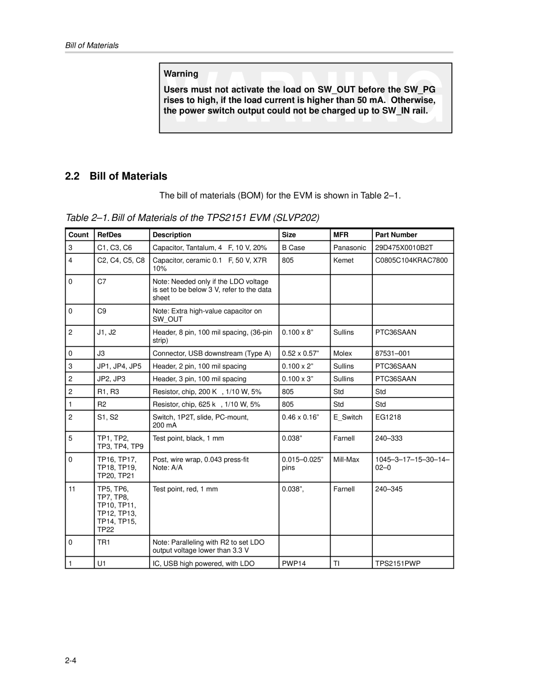
Users must not activate the load on SW_OUT before the SW_PG rises to high, if the load current is higher than 50 mA. Otherwise, the power switch output could not be charged up to SW_IN rail.
2.2 | Bill of Materials |
|
|
| ||
|
|
| The bill of materials (BOM) for the EVM is shown in Table | |||
Table |
|
| ||||
|
|
|
|
|
|
|
Count |
| RefDes | Description | Size | MFR | Part Number |
|
|
|
|
|
|
|
3 |
| C1, C3, C6 | Capacitor, Tantalum, 4 µ F, 10 V, 20% | B Case | Panasonic | 29D475X0010B2T |
4 |
| C2, C4, C5, C8 | Capacitor, ceramic 0.1 µ F, 50 V, X7R | 805 | Kemet | C0805C104KRAC7800 |
|
|
| 10% |
|
|
|
|
|
|
|
|
|
|
0 |
| C7 | Note: Needed only if the LDO voltage |
|
|
|
|
|
| is set to be below 3 V, refer to the data |
|
|
|
|
|
| sheet |
|
|
|
|
|
|
|
|
|
|
0 |
| C9 | Note: Extra |
|
|
|
|
|
| SW_OUT |
|
|
|
|
|
|
|
|
|
|
2 |
| J1, J2 | Header, 8 pin, 100 mil spacing, | 0.100 x 8” | Sullins | PTC36SAAN |
|
|
| strip) |
|
|
|
|
|
|
|
|
|
|
0 |
| J3 | Connector, USB downstream (Type A) | 0.52 x 0.57” | Molex | |
|
|
|
|
|
|
|
3 |
| JP1, JP4, JP5 | Header, 2 pin, 100 mil spacing | 0.100 x 2” | Sullins | PTC36SAAN |
|
|
|
|
|
|
|
2 |
| JP2, JP3 | Header, 3 pin, 100 mil spacing | 0.100 x 3” | Sullins | PTC36SAAN |
|
|
|
|
|
|
|
2 |
| R1, R3 | Resistor, chip, 200 KΩ , 1/10 W, 5% | 805 | Std | Std |
1 |
| R2 | Resistor, chip, 625 kΩ , 1/10 W, 5% | 805 | Std | Std |
|
|
|
|
|
|
|
2 |
| S1, S2 | Switch, 1P2T, slide, | 0.46 x 0.16” | E_Switch | EG1218 |
|
|
| 200 mA |
|
|
|
|
|
|
|
|
|
|
5 |
| TP1, TP2, | Test point, black, 1 mm | 0.038” | Farnell | |
|
| TP3, TP4, TP9 |
|
|
|
|
|
|
|
|
|
|
|
0 |
| TP16, TP17, | Post, wire wrap, 0.043 | |||
|
| TP18, TP19, | Note: A/A | pins |
| |
|
| TP20, TP21 |
|
|
|
|
|
|
|
|
|
|
|
11 |
| TP5, TP6, | Test point, red, 1 mm | 0.038”, | Farnell | |
|
| TP7, TP8, |
|
|
|
|
|
| TP10, TP11, |
|
|
|
|
|
| TP12, TP13, |
|
|
|
|
|
| TP14, TP15, |
|
|
|
|
|
| TP22 |
|
|
|
|
|
|
|
|
|
|
|
0 |
| TR1 | Note: Paralleling with R2 to set LDO |
|
|
|
|
|
| output voltage lower than 3.3 V |
|
|
|
|
|
|
|
|
|
|
1 |
| U1 | IC, USB high powered, with LDO | PWP14 | TI | TPS2151PWP |