Chapter 3
Changeable Components and Test Points
C1, C2, C3, C4— input capacitors, at least 0.047µ F total on each input.
C5, C6, C8, C9— load capacitors, vary according to loads, but C5 plus C6 must be at least 4.7 µ F.
R2— top resistor of the resistor divider, refer to data sheet for its resistance value.
R1— LDO_PG pullup resistor, must be at least 1kΩ .
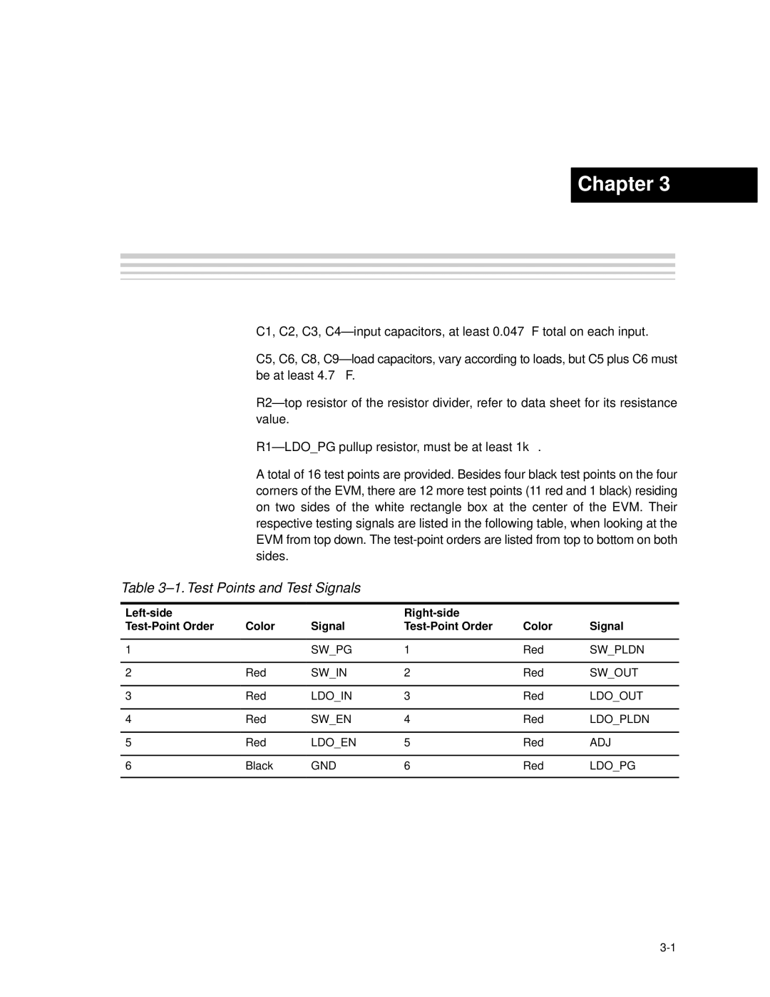
A total of 16 test points are provided. Besides four black test points on the four corners of the EVM, there are 12 more test points (11 red and 1 black) residing on two sides of the white rectangle box at the center of the EVM. Their respective testing signals are listed in the following table, when looking at the EVM from top down. The
Table 3–1. Test Points and Test Signals
|
|
|
|
|
|
| Color | Signal | Color | Signal | |
|
|
|
|
|
|
1 | Red | SW_PG | 1 | Red | SW_PLDN |
|
|
|
|
|
|
2 | Red | SW_IN | 2 | Red | SW_OUT |
|
|
|
|
|
|
3 | Red | LDO_IN | 3 | Red | LDO_OUT |
|
|
|
|
|
|
4 | Red | SW_EN | 4 | Red | LDO_PLDN |
|
|
|
|
|
|
5 | Red | LDO_EN | 5 | Red | ADJ |
|
|
|
|
|
|
6 | Black | GND | 6 | Red | LDO_PG |
|
|
|
|
|
|
Changeable Components and Test Points |
