Chapter 4
EVM Setup
4.1Recommended Test Equipment
The following test equipment is recommended:
∙
∙Current probe
∙Voltage probe
∙3.6 V at
∙
4.2Calculating Voltage Drop and Load Current
The user should read the applicable data sheet before using the EVM.
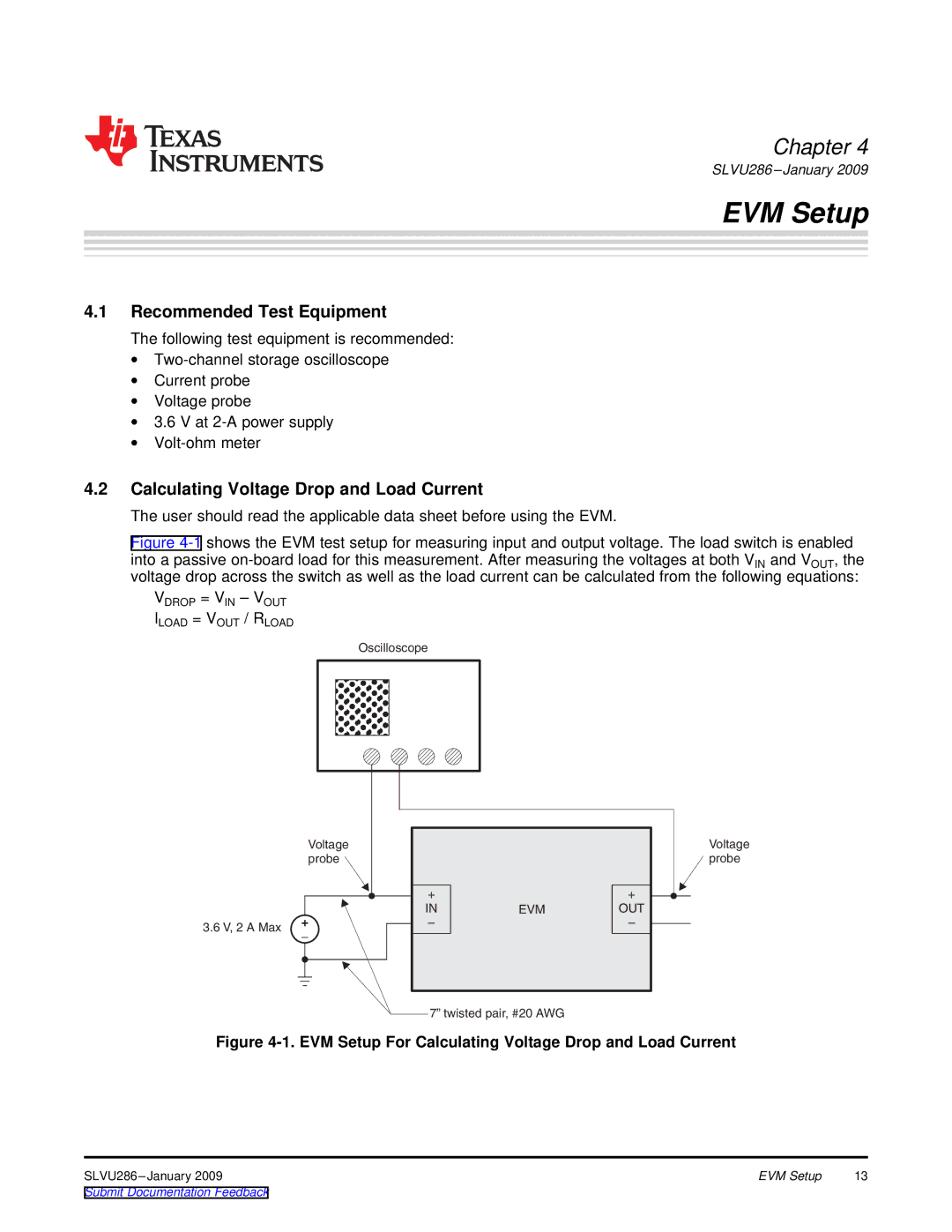
Figure 4-1 shows the EVM test setup for measuring input and output voltage. The load switch is enabled
into a passive on-board load for this measurement. After measuring the voltages at both VIN and VOUT, the voltage drop across the switch as well as the load current can be calculated from the following equations:
VDROP = VIN – VOUT ILOAD = VOUT / RLOAD
3.6 V, 2 A Max
Oscilloscope |
Voltage |
|
|
probe |
|
|
+ |
| + |
IN | EVM | OUT |
– |
| – |
Voltage probe
7” twisted pair, #20 AWG
Figure 4-1. EVM Setup For Calculating Voltage Drop and Load Current
EVM Setup | 13 | |
Submit Documentation Feedback |
|
|