SLUU195 − June 2004
2 |
| Features |
|
|
|
|
|
| |||
|
|
|
|
| Table 1. TPS40090EVM−002 Performance Summary |
|
|
| |||
|
|
|
|
|
|
|
|
|
|
| |
|
|
|
|
| PARAMETER | TEST CONDITIONS | MIN | TYP | MAX | UNITS | |
|
|
| Input voltage range |
|
| 10.5 | 12.0 | 14.0 | V | ||
|
|
| Output voltage set point |
|
| 1.477 | 1.508 | 1.540 | |||
|
|
|
|
|
| ||||||
|
|
| Output current range | VIN = 12 V |
| 0 | 100 | 120 | A | ||
|
|
| Line regulation(1) | IOUT rising from 10 A to 100 A, |
| ±0.1% |
|
| |||
|
|
|
|
|
| 10.5 V ≤ VIN ≤ 14 V |
|
|
|
| |
|
|
| Load regulation | IOUT rising from 10 A to 100 A |
| ±0.3% |
|
| |||
|
|
| Load transient response voltage | IOUT rising from 10 A to 100 A |
| −160 |
| mVPK | |||
|
|
| change | IOUT falling from 100 A to 10 A |
| 200 |
| ||||
|
|
|
|
|
| ||||||
|
|
| Load transient response recovery | IOUT rising from 10 A to 100 A |
| < 10 |
| ∝s | |||
|
|
| time | IOUT falling from 100 A to 10 A |
| < 15 |
| ||||
|
|
|
|
|
| ||||||
|
|
| Loop bandwidth | IOUT = 100 A, | IOUT = 10 A |
| 89 |
| kHz | ||
|
|
| Phase margin | IOUT = 100 A |
|
| 40 |
| ° | ||
|
|
| Input ripple voltage |
|
|
| 80 | 200 | mVPK | ||
|
|
| Output ripple voltage |
|
|
| 15 | 25 | |||
|
|
|
|
|
|
| |||||
|
|
| Output rise time |
|
|
|
|
| ms | ||
|
|
| Operating frequency |
|
| 370 | 418 | 454 | kHz | ||
|
|
| Full load efficiency | VIN = 12 V, | VOUT = 1.5 V, |
| 84.3% |
|
| ||
|
|
| IOUT = 100 A |
|
|
|
| ||||
|
|
|
|
|
|
|
|
|
|
| |
|
|
| Current sharing tolerance | VIN = 12 V, | VOUT = 1.5 V, |
| ±5% | ±10% |
| ||
|
|
|
|
|
| IOUT = 100 A |
|
|
|
|
|
3 |
| Schematic |
|
|
|
|
|
| |||
|
|
|
|
|
|
|
|
|
|
|
|
|
|
|
|
|
|
|
|
|
|
|
|
|
|
|
|
|
|
|
|
|
|
|
|
12V+
+
Phase Programming |
|
|
|
| |
|
|
|
| ||
| R65 | R66 |
| ||
4−phase | open | open |
| ||
3−phase | open | 1k |
| ||
2−phase | 1k | 1k |
| ||
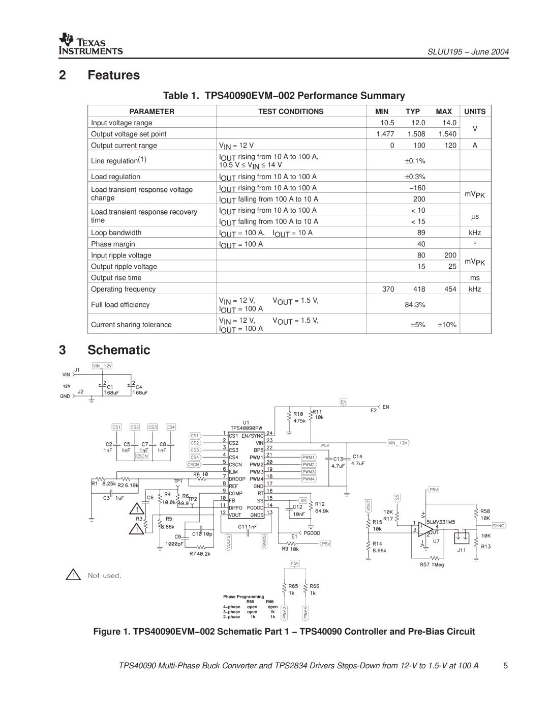
Figure 1. TPS40090EVM−002 Schematic Part 1 − TPS40090 Controller and |
| ||||
TPS40090 | 5 | ||||