www.ti.com
Digital Interface
3Digital Interface
The TSC2007EVM is designed to easily interface with multiple control platforms. Samtec part numbers
|
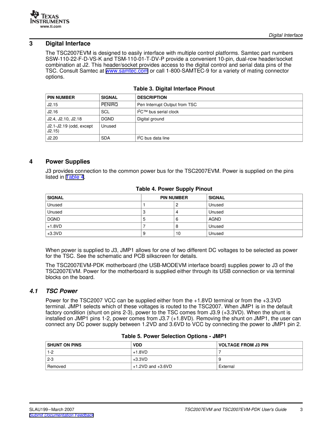
| Table 3. Digital Interface Pinout |
PIN NUMBER | SIGNAL | DESCRIPTION |
J2.15 | PENIRQ | Pen Interrupt Output from TSC |
J2.16 | SCL | I2C™ bus serial clock |
J2.4, J2.10, J2.18 | DGND | Digital ground |
Unused |
| |
J2.15) |
|
|
J2.20 | SDA | I2C bus data line |
4Power Supplies
J3 provides connection to the common power bus for the TSC2007EVM. Power is supplied on the pins listed in Table 4.
Table 4. Power Supply Pinout
SIGNAL |
| PIN NUMBER | SIGNAL |
Unused | 1 | 2 | Unused |
Unused | 3 | 4 | Unused |
DGND | 5 | 6 | AGND |
+1.8VD | 7 | 8 | Unused |
+3.3VD | 9 | 10 | Unused |
When power is supplied to J3, JMP1 allows for one of two different DC voltages to be selected as power for the TSC. See the schematic and PCB silkscreen for details.
The
4.1TSC Power
Power for the TSC2007 VCC can be supplied either from the +1.8VD terminal or from the +3.3VD terminal. JMP1 selects which of these voltages is routed to the TSC2007. When JMP1 is in the default factory condition (shunt on pins
Table 5. Power Selection Options - JMP1
SHUNT ON PINS | VDD | VOLTAGE FROM J3 PIN |
+1.8VD | 7 | |
+3.3VD | 9 | |
Removed | +1.2VD and +3.6VD | External |
SLAU199 | TSC2007EVM and | 3 |
Submit Documentation Feedback |
|
|