Kit Operation
TSC2007EVM
| | | X+ | | | | SDA | | |
| | | | | | | |
| | | X− | | | | | |
| | | | | | SCL | | |
| | | Y+ | | TSC2007 | | |
| | | | | | | | |
| | | Y− | | | | | | |
| | | | | | | | | | |
| | | | | | PENIRQ | | |
| | | AUX | | | | | |
| | | | | | | | | | |
| | | | | | | | | | | |
| | | | | | | | | | | |
| | | | | | | | | | | |
| | | | | | | | | | | |
| | | | | | | | | | | |
| | | | | | | | | | | |
EVM Position 1
| Control Interface |
| SPI, I2C |
| TAS1020B |
EVM Position 2 | USB 8052 |
microcontroller
I2S, AC97
Audio Interface
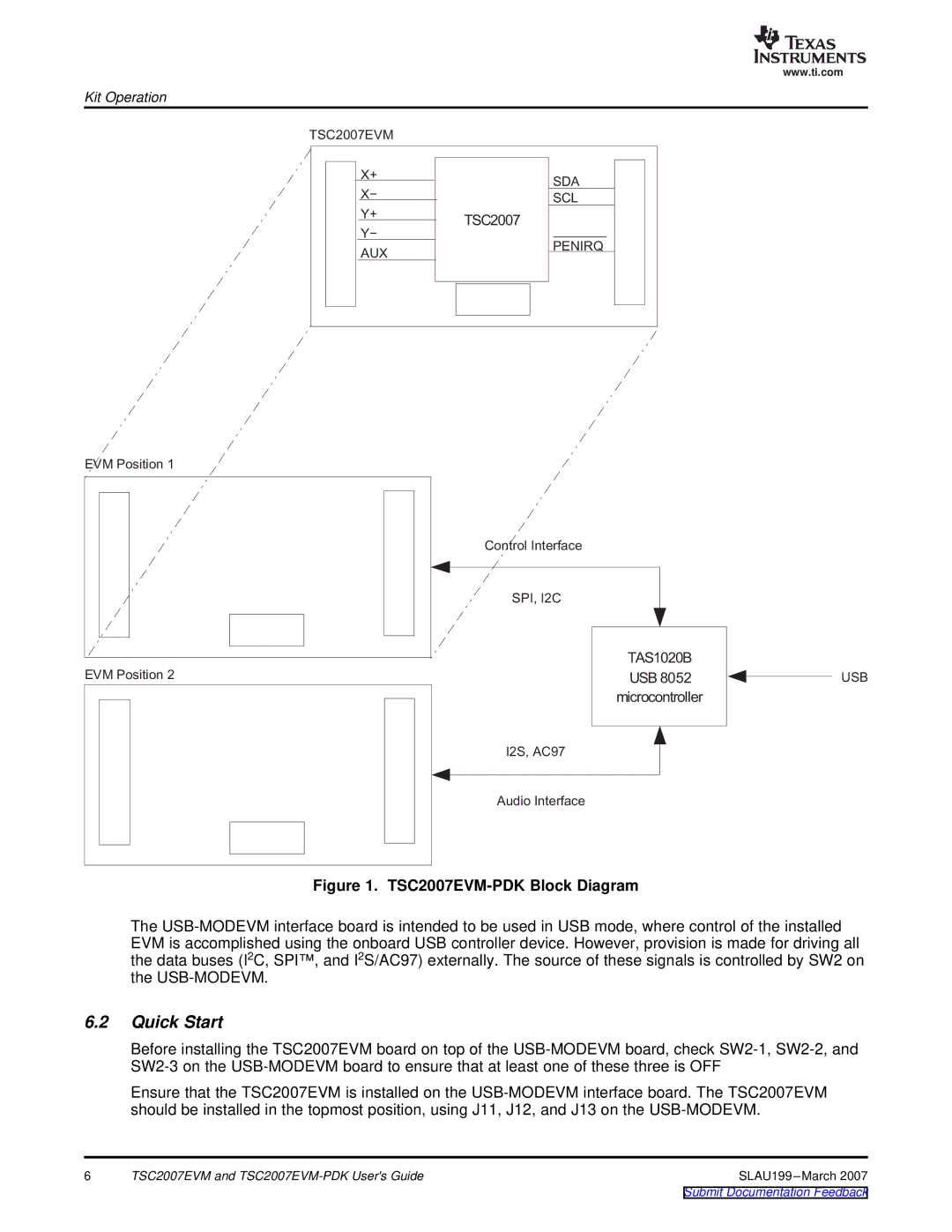
Figure 1. TSC2007EVM-PDK Block Diagram
The USB-MODEVM interface board is intended to be used in USB mode, where control of the installed EVM is accomplished using the onboard USB controller device. However, provision is made for driving all the data buses (I2C, SPI™, and I2S/AC97) externally. The source of these signals is controlled by SW2 on the USB-MODEVM.
6.2Quick Start
Before installing the TSC2007EVM board on top of the USB-MODEVM board, check SW2-1, SW2-2, and SW2-3 on the USB-MODEVM board to ensure that at least one of these three is OFF
Ensure that the TSC2007EVM is installed on the USB-MODEVM interface board. The TSC2007EVM should be installed in the topmost position, using J11, J12, and J13 on the USB-MODEVM.
6 | TSC2007EVM and TSC2007EVM-PDK User's Guide | SLAU199 –March 2007 |
Submit Documentation Feedback