FOR HVAC INSTALLER ONLY
5.(DEH 2000) DIGITAL CONTROL Installation Instructions
Figure 5:
5.1Specifications
Model: 4024539
Electrical: 24 VAC
Humidity Range: 20 – 90%
RH Humidity Accuracy: +/- 4%
Output: 3 Amps 24 VAC
5.2Installation
This control panel must be installed in the conditioned space and in accordance with all applicable codes and standards. Follow the instructions below when installing and setting this control.
5.2A Install Instructions
1.Separate the front panel from the back panel by depressing the tongue located in the bottom of the control.
Figure 6:
2.Gently disconnect the quick connector on the back panel
3.Remove the battery from the back panel by sliding it to the left and out from it’s retaining clip. To mount in the black battery holder on the front panel, insert it from the top, gently pressing downward until it snaps into place and is held under the top clip of the holder. The + engraved on the battery should be visible.
4.Line the back panel up against the wall or flat surface onto which it is to be mounted and drill in the appropriate mounting holes
5.Insert the screws so they extend approximately 1/8" from the wall or flat surface.
6.Align the back panel against these screws, pushing it forward, allowing it to slide downward to lock into position.
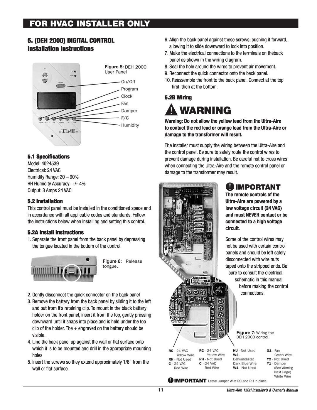
7.Make the electrical connections to the terminals on theback panel as shown in the wiring diagram.
8.Seal the hole around the wires to prevent air movement.
9.Reconnect the quick connector onto the back panel.
10.Reassemble the front to the back panel. Connect at the top first, then at the bottom.
5.2B Wiring
![]() WARNING
WARNING
Warning: Do not allow the yellow lead from the
The installer must supply the wiring between the
![]() IMPORTANT
IMPORTANT
The remote controls of the
Some of the control wires may not be used with certain control panels and should be left safely disconnected with wire nuts taped onto the stripped ends. Be
sure to consult the electrical schematic in this manual
before making the control connections.
Figure 7:
11 |
