Therma-Stor Products Group UA-150H For Hvac Installer Only, Controls, Quiet Installation

Models: UA-150H

1 28
Download 28 pages 61.32 Kb
Page 7
Image 7
3.5 Quiet Installation

FOR HVAC INSTALLER ONLY

3.4E Installation in an Attic with an Existing Forced Air HVAC System

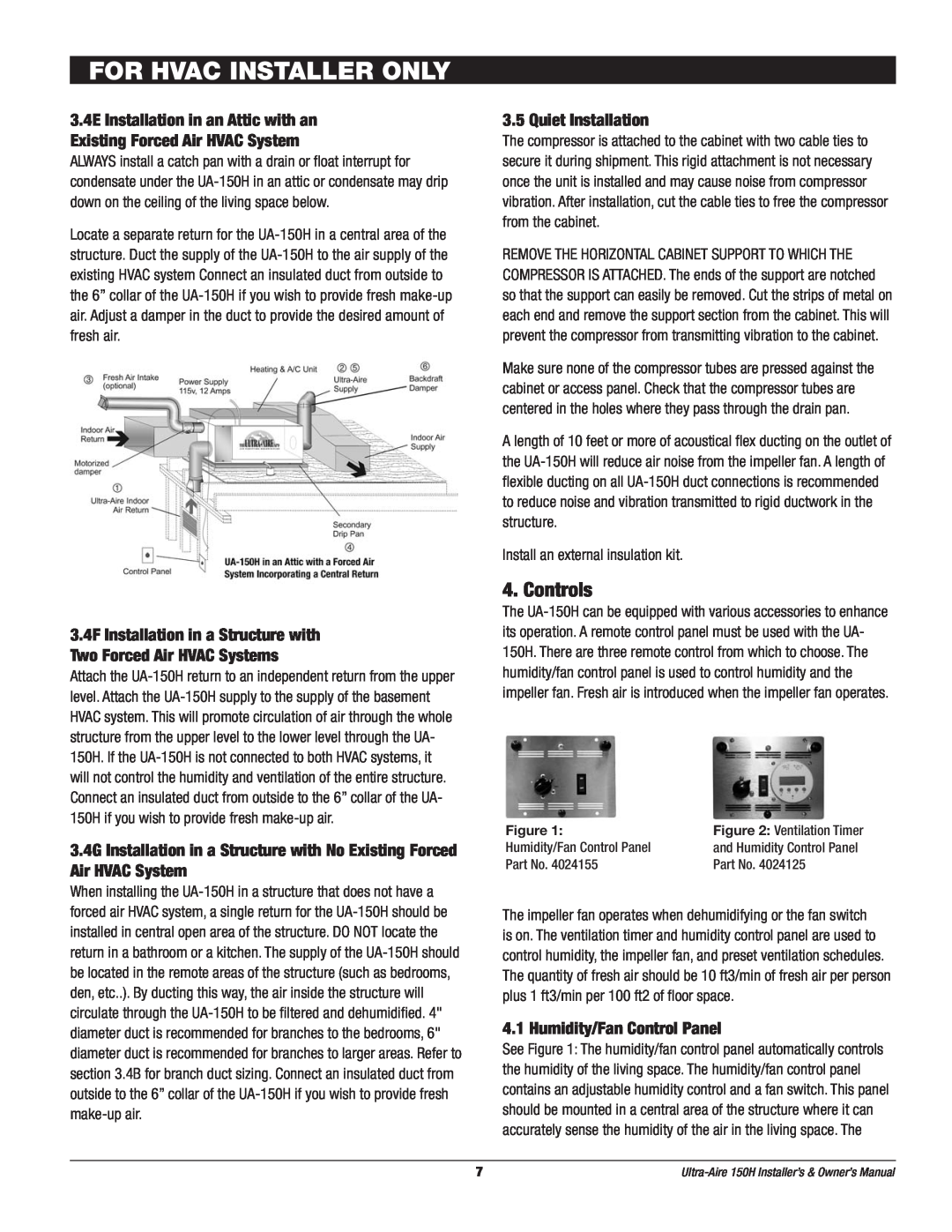
ALWAYS install a catch pan with a drain or float interrupt for condensate under the UA-150H in an attic or condensate may drip down on the ceiling of the living space below.

Locate a separate return for the UA-150H in a central area of the structure. Duct the supply of the UA-150H to the air supply of the existing HVAC system Connect an insulated duct from outside to the 6” collar of the UA-150H if you wish to provide fresh make-up air. Adjust a damper in the duct to provide the desired amount of fresh air.

3.4F Installation in a Structure with Two Forced Air HVAC Systems

Attach the UA-150H return to an independent return from the upper level. Attach the UA-150H supply to the supply of the basement HVAC system. This will promote circulation of air through the whole structure from the upper level to the lower level through the UA- 150H. If the UA-150H is not connected to both HVAC systems, it will not control the humidity and ventilation of the entire structure. Connect an insulated duct from outside to the 6” collar of the UA- 150H if you wish to provide fresh make-up air.

3.4G Installation in a Structure with No Existing Forced Air HVAC System

When installing the UA-150H in a structure that does not have a forced air HVAC system, a single return for the UA-150H should be installed in central open area of the structure. DO NOT locate the return in a bathroom or a kitchen. The supply of the UA-150H should be located in the remote areas of the structure (such as bedrooms, den, etc..). By ducting this way, the air inside the structure will circulate through the UA-150H to be filtered and dehumidified. 4" diameter duct is recommended for branches to the bedrooms, 6" diameter duct is recommended for branches to larger areas. Refer to section 3.4B for branch duct sizing. Connect an insulated duct from outside to the 6” collar of the UA-150H if you wish to provide fresh make-up air.

3.5 Quiet Installation

The compressor is attached to the cabinet with two cable ties to secure it during shipment. This rigid attachment is not necessary once the unit is installed and may cause noise from compressor vibration. After installation, cut the cable ties to free the compressor from the cabinet.

REMOVE THE HORIZONTAL CABINET SUPPORT TO WHICH THE COMPRESSOR IS ATTACHED. The ends of the support are notched so that the support can easily be removed. Cut the strips of metal on each end and remove the support section from the cabinet. This will prevent the compressor from transmitting vibration to the cabinet.

Make sure none of the compressor tubes are pressed against the cabinet or access panel. Check that the compressor tubes are centered in the holes where they pass through the drain pan.

A length of 10 feet or more of acoustical flex ducting on the outlet of the UA-150H will reduce air noise from the impeller fan. A length of flexible ducting on all UA-150H duct connections is recommended to reduce noise and vibration transmitted to rigid ductwork in the structure.

Install an external insulation kit.

4. Controls

The UA-150H can be equipped with various accessories to enhance its operation. A remote control panel must be used with the UA- 150H. There are three remote control from which to choose. The humidity/fan control panel is used to control humidity and the impeller fan. Fresh air is introduced when the impeller fan operates.


Figure 1:

Figure 2: Ventilation Timer

Humidity/Fan Control Panel

and Humidity Control Panel

Part No. 4024155

Part No. 4024125


The impeller fan operates when dehumidifying or the fan switch is on. The ventilation timer and humidity control panel are used to control humidity, the impeller fan, and preset ventilation schedules. The quantity of fresh air should be 10 ft3/min of fresh air per person plus 1 ft3/min per 100 ft2 of floor space.

4.1 Humidity/Fan Control Panel

See Figure 1: The humidity/fan control panel automatically controls the humidity of the living space. The humidity/fan control panel contains an adjustable humidity control and a fan switch. This panel should be mounted in a central area of the structure where it can accurately sense the humidity of the air in the living space. The

7

Ultra-Aire 150H Installer’s & Owner’s Manual

Page 7
Image 7
Therma-Stor Products Group UA-150H For Hvac Installer Only, Controls, Quiet Installation, Humidity/Fan Control Panel