ToughpowerTM 700W / 800W | ToughpowerTM 700W / 800W |
3. Power Connector Introduction | 4. Installation Steps |
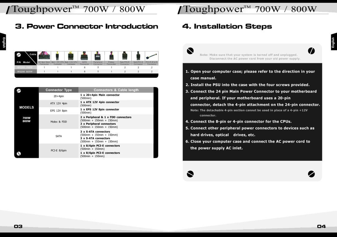
Cable
P/N Model | 20+4pin Main | 4pin +12V CPU | 8pin +12V CPU | SATA | Peripheral | Floppy | 8pin | 6pin | ||
|
| Connector | Connector | Connector | Connector | Connector | Connector | Connector | Connector | Connector |
W0295 | 700W | 1 | 1 | 1 | 6 | 5 | 1 | 2 | 2 | 2 |
W0296 | 800W | 1 | 1 | 1 | 6 | 5 | 1 | 2 | 2 | 2 |
Note: Make sure that your system is turned off and unplugged. Disconnect the AC power cord from your old power supply.
1. | Open your computer case; please refer to the direction in your |
| case manual. |
2. | Install the PSU into the case with the four screws provided. |
Connector Type
20+4pin
| ATX 12V | 4pin |
MODELS | EPS 12V | 8pin |
| ||
700W |
|
|
800W | Molex & FDD | |
SATA
Connectors & Cable length
1 x 20+4pin Main connector
(500mm)
1 x ATX 12V 4pin connector
(500mm)
1 x EPS 12V 8pin connector
(500mm)
2 x Peripheral & 1 x FDD connectors (500mm + 150mm + 150mm)
3 x Peripheral connectors
(500mm + 150mm + 150mm)
3 x
(500mm + 150mm + 150mm)
3 x
(500mm + 150mm + 150mm)
1 x 8/6pin
(500mm + 150mm)
1 x 8/6pin
(500mm + 150mm)
3. Connect the 24 pin Main Power Connector to your motherboard |
and peripheral. If your motherboard uses a |
connector, detach the
Note: The detachable
connector.
4.Connect the
5.Connect other peripheral power connectors to devices such as
hard drives, optical drives, etc.
6.Close your computer case and connect the AC power cord to the power supply AC inlet.
03 | 04 |