L1
TH
C
HL
|
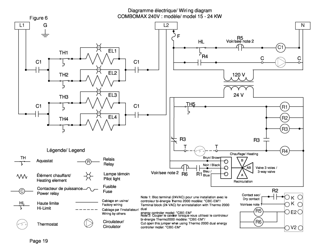
| Diagramme électrique/ Wiri ng diagram |
|
|
Figure 6 |
| COMBOMAX 240V : modèle/ model 15 - 24 KW |
|
|
G |
| L2 |
| N |
|
| F | R5 |
|
|
| HL | Voir/see note 2 | C1 |
| TH1 | EL1 |
| |
|
|
| ||
| R4 | C | C | |
|
| |||
C1 |
| C1 | ||
|
|
| ||
| TH2 | EL2 | 120 V |
|
|
|
| ||
| TH3 | EL3 | 24 V |
|
|
|
|
|
C1 | C1 | TH5 | R1 |
| |||
TH4 | EL4 |
| R2 |
|
|
| R3 |
|
|
| R3 |
|
| R3 |
|
Légende/ Legend |
|
| T | T |
|
| R4 |
|
|
|
| Chauffage/ Heating | |||
|
|
|
| Brun/ Brown |
| ||
Aquastat | R | Relais |
| B |
|
| |
|
|
|
| ||||
Relay |
| Noir / Black |
|
| |||
|
|
| AB | Valve 3 voies / |
| ||
|
|
|
| R1 BlueBleu / |
| ||
Élément chauffant/ |
| Lampe témoin | Voir/see note 2 R6 | A |
| ||
Heating element |
| Pilot light |
|
| Recirculation |
|
|
|
|
|
|
|
| ||
Contacteur de puissance |
| Fusible |
|
|
| R2 |
|
| Fuse |
|
|
|
| ||
Power relay |
|
|
|
|
| ||
|
| Note 1: Bloc terminal (24VAC) pour une installation avec le | Contact sec/ | K | |||
|
| Cablage en usine/ | Dry contact | ||||
Haute limite |
| controleur | Voir/see note 1 | K | |||
| Factory wiring | Terminal block (24 VAC) for aninstallation with Thermo 2000 | |||||
| Cablage par l'installateur/ | dual |
|
| R5 | E2 | |
|
| Wiring by others | energy controller model: |
|
| ||
|
|
| Note 2: Couper le cavalier lorsque vous utilisez le controleur |
|
|
| |
|
| Circulateur/ |
| R6 |
| ||
Thermostat |
| Cut open this jumper when using Thermo 2000 dual energy |
|
| |||
| Circulator | controller model: |
|
|
| V2 | |
|
|
|
|
| |||
Page 19