Pump flow rate = Boiler output ⎟ BWTD ⎟ 500
•Pump flow rate is expressed in U.S. gallons per minute or GPM.
•The Boiler output ( in net BTU per hour) is the maximum amount of heat to be transferred through the heating circuit to meet the hot water demand.
•BWTD is the boiler water temperature drop through the heating circuit.
For example, a 24 Kw COMBOMAXMC boiler has a rated output of 81,964 BTU/hour. The system is designed for a boiler water temperature drop (BWTD) of 20°F.
Pump flow rate = 81,964 ⎟ 20 ⎟ 500 = 8,2 GPM.
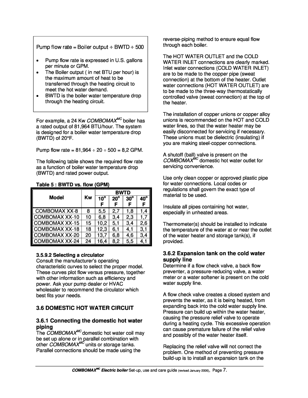
The following table shows the required flow rate as a function of boiler water temperature drop (BWTD) and rated power output.
Table 5 : BWTD vs. flow (GPM)
|
|
|
|
|
|
|
| Model | Kw |
| BWTD |
| |
| 10o | 20o | 30o | 40o | ||
|
|
| F | F | F | F |
| COMBOMAX | 8 | 5,5 | 2,7 | 1,8 | 1,4 |
| COMBOMAX | 10 | 6,8 | 3,4 | 2,3 | 1,7 |
| COMBOMAX | 15 | 10,2 | 5,1 | 3,4 | 2,6 |
| COMBOMAX | 18 | 12,3 | 6,1 | 4,1 | 3,1 |
| COMBOMAX | 20 | 13,7 | 6,8 | 4,6 | 3,4 |
| COMBOMAX | 24 | 16,4 | 8,2 | 5,5 | 4,1 |
3.5.9.2Selecting a circulator Consult the manufacturer’s operating characteristic curves to select the proper model. These curves plot flow versus pressure, together with other information such as efficiency and power. Ask your pump dealer or HVAC wholesaler to recommend the circulator which best fits your needs.
3.6 DOMESTIC HOT WATER CIRCUIT
3.6.1Connecting the domestic hot water piping
The COMBOMAXMC domestic hot water coil may be set up alone or in parallel combination with other COMBOMAXMC units or storage tanks. Parallel connections should be made using the
The HOT WATER OUTLET and the COLD WATER INLET connections are clearly marked. Inlet water connections (COLD WATER INLET) are to be made to the copper pipe (sweat connection) at the bottom of the heater. Outlet water connections (HOT WATER OUTLET) are to be made to the
The installation of copper unions or copper alloy unions is recommended on the HOT and COLD water lines, so that the water heater may be easily disconnected for servicing if necessary. These unions must be dielectric (insulating) if you are making
A shutoff (ball) valve is present on the COMBOMAXMC domestic hot water outlet for servicing convenience.
Use only clean copper or approved plastic pipe for water connections. Local codes or regulations shall govern the exact type of material to be used.
Insulate all pipes containing hot water, especially in unheated areas.
Thermometer(s) should be installed to indicate the temperature of the water at or near the outlet of the water heater and storage tank(s), if provided.
3.6.2Expansion tank on the cold water supply line
Determine if a flow check valve, a back flow preventer, a
A flow check valve creates a closed system and prevents the water, as it is being heated, from expanding back into the cold water supply line. Pressure can build up within the water heater, causing the pressure relief valve to operate during a heating cycle. This excessive operation can cause premature failure of the relief valve and possibly of the water heater itself.
Replacing the relief valve will not correct the problem. One method of preventing pressure
COMBOMAXMC Electric boiler