All installations and services must be performed by qualified service personnel.
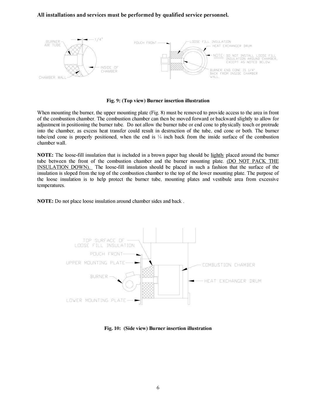
Fig. 9: (Top view) Burner insertion illustration
When mounting the burner, the upper mounting plate (Fig. 8) must be removed to provide access to the area in front of the combustion chamber. The combustion chamber can then be moved forward or backward slightly to allow for adjustment in positioning the burner tube. Do not allow the burner tube or end cone to physically touch or protrude into the chamber, as excess heat transfer could result in destruction of the tube, end cone or both. The burner tube/end cone is properly positioned, when the end is ¼ inch back from the inside surface of the combustion chamber wall.
NOTE: The
NOTE: Do not place loose insulation around chamber sides and back .
Fig. 10: (Side view) Burner insertion illustration
6