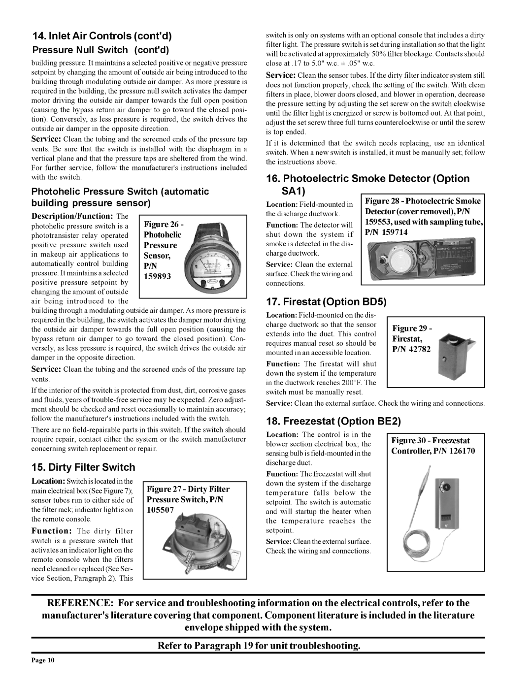
Figure 26 -
Photohelic
Pressure
Sensor,
P/N
159893

14.Inlet Air Controls (cont'd)

Pressure Null Switch (cont'd)

building pressure. It maintains a selected positive or negative pressure setpoint by changing the amount of outside air being introduced to the building through modulating outside air damper. As more pressure is required in the building, the pressure null switch activates the damper motor driving the outside air damper towards the full open position (causing the bypass return air damper to go toward the closed posi- tion). Conversely, as less pressure is required, the switch drives the outside air damper in the opposite direction.

Service: Clean the tubing and the screened ends of the pressure tap vents. Be sure that the switch is installed with the diaphragm in a vertical plane and that the pressure taps are sheltered from the wind. For further service, follow the manufacturer's instructions included with the switch.

Photohelic Pressure Switch (automatic building pressure sensor)

Description/Function: The photohelic pressure switch is a phototransister relay operated positive pressure switch used in makeup air applications to automatically control building pressure. It maintains a selected positive pressure setpoint by changing the amount of outside air being introduced to the

building through a modulating outside air damper. As more pressure is required in the building, the switch activates the damper motor driving the outside air damper towards the full open position (causing the bypass return air damper to go toward the closed position). Con- versely, as less pressure is required, the switch drives the outside air damper in the opposite direction.

Service: Clean the tubing and the screened ends of the pressure tap vents.

If the interior of the switch is protected from dust, dirt, corrosive gases and fluids, years of trouble-free service may be expected. Zero adjust- ment should be checked and reset occasionally to maintain accuracy; follow the manufacturer's instructions included with the switch.

switch is only on systems with an optional console that includes a dirty filter light. The pressure switch is set during installation so that the light will be activated at approximately 50% filter blockage. Contacts should close at .17 to 5.0" w.c. ± .05" w.c.

Service: Clean the sensor tubes. If the dirty filter indicator system still does not function properly, check the setting of the switch. With clean filters in place, blower doors closed, and blower in operation, decrease the pressure setting by adjusting the set screw on the switch clockwise until the filter light is energized or screw is bottomed out. At that point, adjust the set screw three full turns counterclockwise or until the screw is top ended.

If it is determined that the switch needs replacing, use an identical switch. When a new switch is installed, it must be manually set; follow the instructions above.

16. Photoelectric Smoke Detector (Option

SA1)


Location: Field-mounted in


Figure 28 - Photoelectric Smoke


Detector (cover removed), P/N

the discharge ductwork.


Function: The detector will


159553, used with sampling tube,


P/N 159714

shut down the system if


smoke is detected in the dis-


charge ductwork.


Service: Clean the external


surface. Check the wiring and


connections.


17. Firestat (Option BD5)


Location: Field-mounted on the dis-


charge ductwork so that the sensor

Figure 29 -

extends into the duct. This control

Firestat,

requires manual reset so should be

P/N 42782

mounted in an accessible location.


Function: The firestat will shut


down the system if the temperature


in the ductwork reaches 200°F. The


switch must be manually reset.


Service: Clean the external surface. Check the wiring and connections.

18. Freezestat (Option BE2)

There are no field-repairable parts in this switch. If the switch should require repair, contact either the system or the switch manufacturer concerning switch replacement or repair.

Location: The control is in the blower section electrical box; the sensing bulb is field-mounted in the

Figure 30 - Freezestat Controller, P/N 126170

15. Dirty Filter Switch

Location: Switch is located in the main electrical box (See Figure 7); sensor tubes run to either side of the filter rack; indicator light is on the remote console.

Function: The dirty filter switch is a pressure switch that activates an indicator light on the remote console when the filters need cleaned or replaced (See Ser- vice Section, Paragraph 2). This

Figure 27 - Dirty Filter Pressure Switch, P/N 105507

discharge duct.

Function: The freezestat will shut down the system if the discharge temperature falls below the setpoint. The switch is automatic and will startup the heater when the temperature reaches the setpoint.

Service: Clean the external surface. Check the wiring and connections.

REFERENCE: For service and troubleshooting information on the electrical controls, refer to the manufacturer's literature covering that component. Component literature is included in the literature envelope shipped with the system.

Refer to Paragraph 19 for unit troubleshooting.

Page 10

Page 10
Image 10
Thomas & Betts RZ-NA 441-OMS Inlet Air Controls contd, Photoelectric Smoke Detector Option SA1, Firestat Option BD5

RZ-NA 441-OMS specifications

The Thomas & Betts RZ-NA 441-OMS is a cutting-edge component designed for advanced electrical applications, known for its reliability and performance. This product stands out in the market due to its innovative features and robust design, making it ideal for a variety of industrial and commercial uses.

One of the main features of the RZ-NA 441-OMS is its superior connectivity capabilities. The component is engineered to provide seamless integration with multiple electrical systems, ensuring efficient power distribution and minimal downtime. The versatility of this device enables it to be utilized in various setups, including complex machinery and sophisticated automation processes.

Another notable characteristic of the RZ-NA 441-OMS is its remarkable insulation properties. The device is built with high-quality materials that enhance its thermal stability and resistance to environmental factors. This ensures that it can withstand harsh conditions while maintaining optimal functionality, making it a reliable choice for outdoor applications and areas with extreme temperatures.

The RZ-NA 441-OMS also incorporates advanced safety features, such as overcurrent protection and fault detection systems. These technologies are designed to prevent electrical failures, safeguarding both the equipment and personnel involved. This emphasis on safety aligns with Thomas & Betts’ commitment to providing reliable solutions that prioritize user protection and system integrity.

In terms of installation, the RZ-NA 441-OMS is designed for ease of use. Its compact design allows for quick and straightforward mounting, saving valuable time during setup. Additionally, it features customizable configurations, making it suitable for various application needs. This flexibility is particularly beneficial for companies seeking to optimize their operations while ensuring compatibility with existing infrastructure.

Moreover, the RZ-NA 441-OMS is supported by extensive documentation and customer service, ensuring that users have access to the information and assistance they need for effective implementation and troubleshooting.

Overall, the Thomas & Betts RZ-NA 441-OMS represents a significant advancement in electrical connectivity solutions, combining robustness, versatility, and safety in a single package. Its innovative features make it an essential component for businesses looking to enhance their electrical systems reliably and efficiently.