RZ-NA 441-OMS specifications
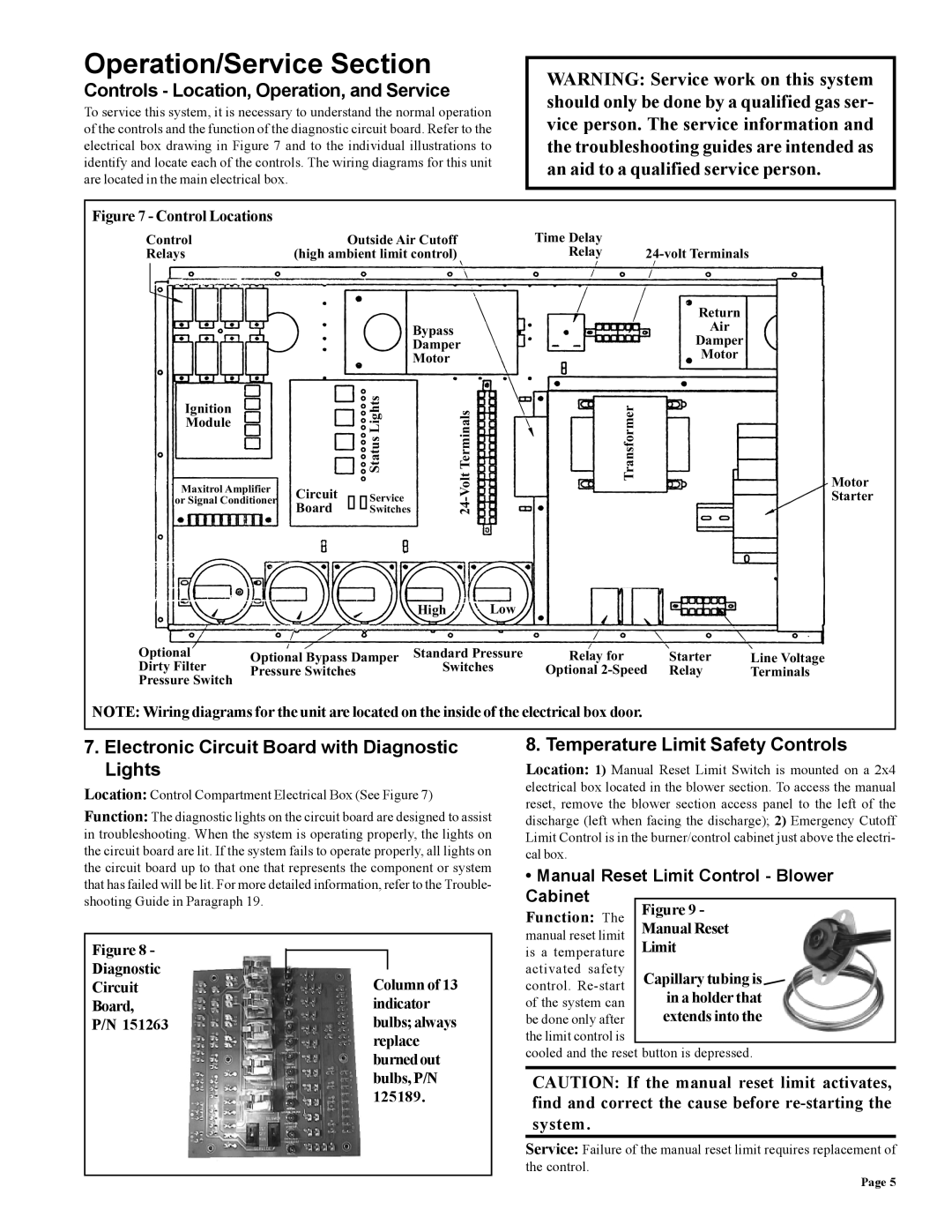
The Thomas & Betts RZ-NA 441-OMS is a cutting-edge component designed for advanced electrical applications, known for its reliability and performance. This product stands out in the market due to its innovative features and robust design, making it ideal for a variety of industrial and commercial uses.One of the main features of the RZ-NA 441-OMS is its superior connectivity capabilities. The component is engineered to provide seamless integration with multiple electrical systems, ensuring efficient power distribution and minimal downtime. The versatility of this device enables it to be utilized in various setups, including complex machinery and sophisticated automation processes.
Another notable characteristic of the RZ-NA 441-OMS is its remarkable insulation properties. The device is built with high-quality materials that enhance its thermal stability and resistance to environmental factors. This ensures that it can withstand harsh conditions while maintaining optimal functionality, making it a reliable choice for outdoor applications and areas with extreme temperatures.
The RZ-NA 441-OMS also incorporates advanced safety features, such as overcurrent protection and fault detection systems. These technologies are designed to prevent electrical failures, safeguarding both the equipment and personnel involved. This emphasis on safety aligns with Thomas & Betts’ commitment to providing reliable solutions that prioritize user protection and system integrity.
In terms of installation, the RZ-NA 441-OMS is designed for ease of use. Its compact design allows for quick and straightforward mounting, saving valuable time during setup. Additionally, it features customizable configurations, making it suitable for various application needs. This flexibility is particularly beneficial for companies seeking to optimize their operations while ensuring compatibility with existing infrastructure.
Moreover, the RZ-NA 441-OMS is supported by extensive documentation and customer service, ensuring that users have access to the information and assistance they need for effective implementation and troubleshooting.
Overall, the Thomas & Betts RZ-NA 441-OMS represents a significant advancement in electrical connectivity solutions, combining robustness, versatility, and safety in a single package. Its innovative features make it an essential component for businesses looking to enhance their electrical systems reliably and efficiently.

