R1. Drive Components

The blower, motor and drive components are located in the blower cabinet at the top of the system. Systems with horizontal discharge have a cabinet with eight removable door panels. Systems with vertical discharge have a cabinet with six removable door panels. Remove the panels required to access the components being serviced.

1A. Blower Bearings

All blowers are Class I with pillow block bearings. Clean the fitting and add type NLG-2 or -2 standard grade grease. Add grease with a handgun until a slight bead of grease forms at the seal. Be careful not to unseat the seal by over lubricating.

NOTE: If unusual environmental conditions exist (temperatures below 32oF or above 200oF; moisture; or contaminants) more frequent lubri- cation is required.

CAUTION: If the blower is unused for more than three months, the bearings should be purged with new grease prior to startup.

Recommended Bearing Lubrication Schedule in Months


Bearing Bore Diameter (Inches)

RPM

1/2

>1 to

>1-1/2 to


to 1

1-1/2

1-15/16


to 500

6

6

6

501 - 1000

6

6

6

1001 - 1500

5

5

5

1501 - 2000

5

4

5

1B. Blower Belts

Check belts for proper tension and wear. Adjust belt tension as needed. Replace worn belts.

Proper belt tension is important to the long life of the belt and motor. A loose belt will cause wear and slippage. Too much tension will cause

excessive motor and blower bearing wear. If adjustment is required, adjust belt tension by means of the adjusting screw on the motor base until the belt can be depressed 1/2" to 3/4" (Figure 2). Tighten the lock nut on the adjusting screw. Be sure the belt is aligned in the pulleys.

Figure 2 -


Belt

3/4” (19mm)

Tension


R E 2. Filters

If the system includes filters, check the filters quarterly. Filters could be either in the optional inlet base or in an optional filter cabinet.

If the filters are in the perimeter of the inlet base; they are two-inch permanent filters. Remove and clean the filters as needed.

If the filters are in a filter cabinet (the filter cabinet is always between the inlet base and the burner/control section), remove the filter cabinet door panels to access the V-bank filter rack. Filters may be either 2" disposable, 1" or 2" permanent, or 1" or 2" disposable pleated. Clean or replace as needed.

Sizes and Quantity of Filters in the Filter Cabinet

( same for all types of filters)

Size

109

112

115

118

122

125

16" x 16"

4

4

-

-

16

16

16" x 20"

4

4

6

6

-

-

16" x 25"

-

-

6

6

8

8

S3. Manifold Gas Pressure

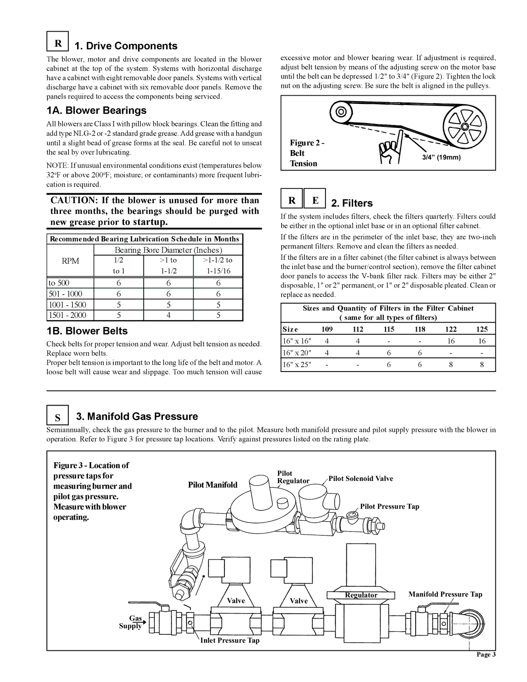
Semiannually, check the gas pressure to the burner and to the pilot. Measure both manifold pressure and pilot supply pressure with the blower in operation. Refer to Figure 3 for pressure tap locations. Verify against pressures listed on the rating plate.

Figure 3 - Location of

pressure taps for


Pilot

Pilot Solenoid Valve

Pilot Manifold

Regulator

measuring burner and


pilot gas pressure.


Measure with blower


Pilot Pressure Tap

operating.


Valve

Valve

Regulator

Manifold Pressure Tap


Gas


Supply


Inlet Pressure Tap


Page 3

Page 3
Image 3
Thomas & Betts RZ-NA 441-OMS Drive Components, 1A. Blower Bearings, 1B. Blower Belts, Filters, Manifold Gas Pressure

RZ-NA 441-OMS specifications

The Thomas & Betts RZ-NA 441-OMS is a cutting-edge component designed for advanced electrical applications, known for its reliability and performance. This product stands out in the market due to its innovative features and robust design, making it ideal for a variety of industrial and commercial uses.

One of the main features of the RZ-NA 441-OMS is its superior connectivity capabilities. The component is engineered to provide seamless integration with multiple electrical systems, ensuring efficient power distribution and minimal downtime. The versatility of this device enables it to be utilized in various setups, including complex machinery and sophisticated automation processes.

Another notable characteristic of the RZ-NA 441-OMS is its remarkable insulation properties. The device is built with high-quality materials that enhance its thermal stability and resistance to environmental factors. This ensures that it can withstand harsh conditions while maintaining optimal functionality, making it a reliable choice for outdoor applications and areas with extreme temperatures.

The RZ-NA 441-OMS also incorporates advanced safety features, such as overcurrent protection and fault detection systems. These technologies are designed to prevent electrical failures, safeguarding both the equipment and personnel involved. This emphasis on safety aligns with Thomas & Betts’ commitment to providing reliable solutions that prioritize user protection and system integrity.

In terms of installation, the RZ-NA 441-OMS is designed for ease of use. Its compact design allows for quick and straightforward mounting, saving valuable time during setup. Additionally, it features customizable configurations, making it suitable for various application needs. This flexibility is particularly beneficial for companies seeking to optimize their operations while ensuring compatibility with existing infrastructure.

Moreover, the RZ-NA 441-OMS is supported by extensive documentation and customer service, ensuring that users have access to the information and assistance they need for effective implementation and troubleshooting.

Overall, the Thomas & Betts RZ-NA 441-OMS represents a significant advancement in electrical connectivity solutions, combining robustness, versatility, and safety in a single package. Its innovative features make it an essential component for businesses looking to enhance their electrical systems reliably and efficiently.