6. INSTALLATION
6.1. Contents
Check to be sure that the following components are available in a complete set before installation: |
| |||
Speaker | 1 Mounting bracket ..... 1 Front grille | 1 Cutout template | 1 Anchor piece | 2 |
Stud holder | 4 | Masking tape | 4 | Mounting screws/washers |
| |
|
| "Short"... 2 |
| Tapping screw (3x8) .... 4 | Screw (M4x30) .... | 6 |
|
| "Long"... | 2 | Screw (M5x10) .... 4 |
|
|
|
|
|
| Spring washer .... | 4 | |
|
|
|
|
| ||
|
|
|
| Plain washer | .... 4 |
|
6.2. Flush Wall or Ceiling Mounting
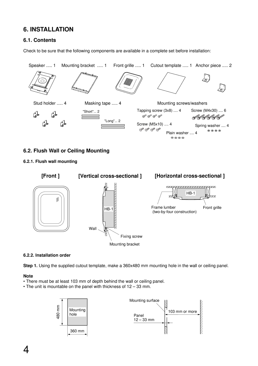
6.2.1. Flush wall mounting
[Front ] | [Vertical | [Horizontal |
Wall
Frame lumber | Front grille |
|
Fixing screw
Mounting bracket
6.2.2. Installation order
Step 1. Using the supplied cutout template, make a 360x480 mm mounting hole in the wall or ceiling panel.
Note
•There must be at least 103 mm of depth behind the wall or ceiling panel.
•The unit is mountable on the panel with thickness of 12 – 33 mm.
480 mm
Mounting hole
Mounting surface
Panel
12 – 33 mm
103 mm or more
360 mm
4