TROUBLESHOOTING THE ELECTRONIC IGNITION SYSTEM
Note: Before troubleshooting, be sure that the appliance main line gas
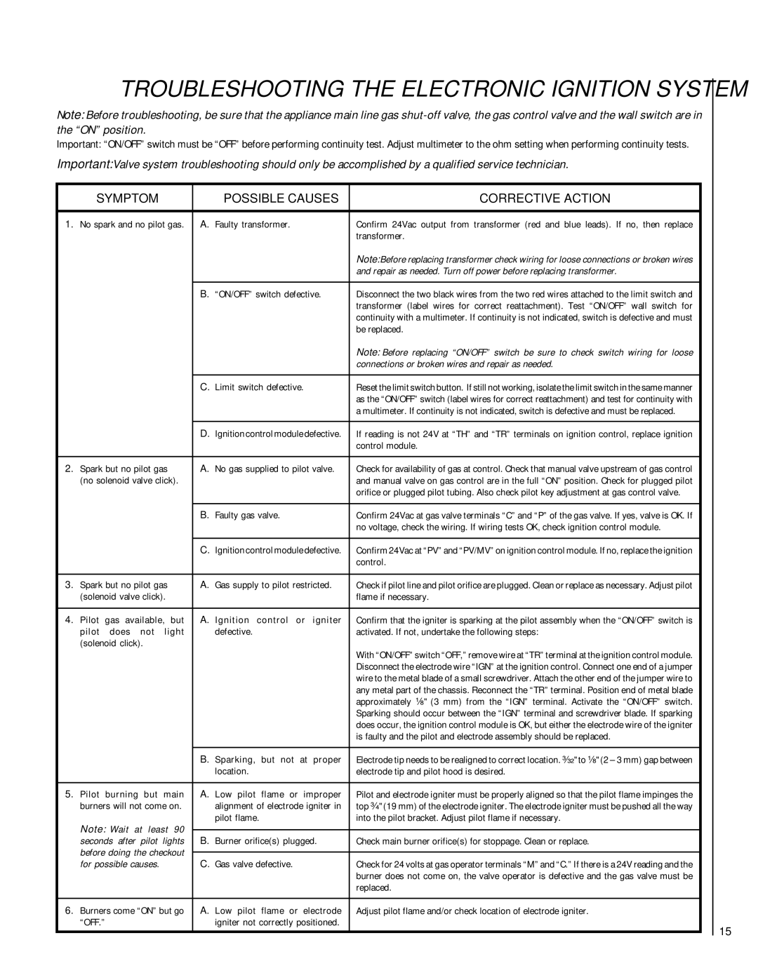
Important: “ON/OFF” switch must be “OFF” before performing continuity test. Adjust multimeter to the ohm setting when performing continuity tests.
Important: Valve system troubleshooting should only be accomplished by a qualified service technician.
SYMPTOM |
| POSSIBLE CAUSES | CORRECTIVE ACTION | |
1. No spark and no pilot gas. | A. Faulty transformer. | Confirm 24Vac output from transformer (red and blue leads). If no, then replace | ||
|
|
|
| transformer. |
|
|
|
| Note: Before replacing transformer check wiring for loose connections or broken wires |
|
|
|
| and repair as needed. Turn off power before replacing transformer. |
|
|
|
|
|
|
|
| B. “ON/OFF” switch defective. | Disconnect the two black wires from the two red wires attached to the limit switch and |
|
|
|
| transformer (label wires for correct reattachment). Test “ON/OFF” wall switch for |
|
|
|
| continuity with a multimeter. If continuity is not indicated, switch is defective and must |
|
|
|
| be replaced. |
|
|
|
| Note: Before replacing “ON/OFF” switch be sure to check switch wiring for loose |
|
|
|
| connections or broken wires and repair as needed. |
|
|
|
|
|
|
|
| C. Limit switch defective. | Reset the limit switch button. If still not working, isolate the limit switch in the same manner |
|
|
|
| as the “ON/OFF” switch (label wires for correct reattachment) and test for continuity with |
|
|
|
| a multimeter. If continuity is not indicated, switch is defective and must be replaced. |
|
|
|
|
|
|
|
| D. Ignition control module defective. | If reading is not 24V at “TH” and “TR” terminals on ignition control, replace ignition |
|
|
|
| control module. |
|
|
| ||
2. Spark but no pilot gas | A. No gas supplied to pilot valve. | Check for availability of gas at control. Check that manual valve upstream of gas control | ||
(no solenoid valve click). |
| and manual valve on gas control are in the full “ON” position. Check for plugged pilot | ||
|
|
|
| orifice or plugged pilot tubing. Also check pilot key adjustment at gas control valve. |
|
|
|
|
|
|
|
| B. Faulty gas valve. | Confirm 24Vac at gas valve terminals “C” and “P” of the gas valve. If yes, valve is OK. If |
|
|
|
| no voltage, check the wiring. If wiring tests OK, check ignition control module. |
|
|
|
|
|
|
|
| C. Ignition control module defective. | Confirm 24Vac at “PV” and “PV/MV” on ignition control module. If no, replace the ignition |
|
|
|
| control. |
|
|
| ||
3. Spark but no pilot gas | A. Gas supply to pilot restricted. | Check if pilot line and pilot orifice are plugged. Clean or replace as necessary. Adjust pilot | ||
(solenoid valve click). |
| flame if necessary. | ||
|
|
| ||
4. Pilot gas available, but | A. Ignition control or igniter | Confirm that the igniter is sparking at the pilot assembly when the “ON/OFF” switch is | ||
pilot does | not | light | defective. | activated. If not, undertake the following steps: |
(solenoid click). |
|
| With “ON/OFF” switch “OFF,” remove wire at “TR” terminal at the ignition control module. | |
|
|
|
| |
|
|
|
| Disconnect the electrode wire “IGN” at the ignition control. Connect one end of a jumper |
|
|
|
| wire to the metal blade of a small screwdriver. Attach the other end of the jumper wire to |
|
|
|
| any metal part of the chassis. Reconnect the “TR” terminal. Position end of metal blade |
|
|
|
| approximately ¹⁄₈" (3 mm) from the “IGN” terminal. Activate the “ON/OFF” switch. |
|
|
|
| Sparking should occur between the “IGN” terminal and screwdriver blade. If sparking |
|
|
|
| does occur, the ignition control module is OK, but either the electrode wire of the igniter |
|
|
|
| is faulty and the pilot and electrode assembly should be replaced. |
|
|
|
|
|
|
|
| B. Sparking, but not at proper | Electrode tip needs to be realigned to correct location. ³⁄₃₂" to ¹⁄₈" (2 – 3 mm) gap between |
|
|
| location. | electrode tip and pilot hood is desired. |
|
|
| ||
5. Pilot burning but main | A. Low pilot flame or improper | Pilot and electrode igniter must be properly aligned so that the pilot flame impinges the | ||
burners will not come on. | alignment of electrode igniter in | top ³⁄₄" (19 mm) of the electrode igniter. The electrode igniter must be pushed all the way | ||
Note: Wait at least 90 | pilot flame. | into the pilot bracket. Adjust pilot flame if necessary. | ||
|
| |||
|
| |||
seconds after | pilot | lights | B. Burner orifice(s) plugged. | Check main burner orifice(s) for stoppage. Clean or replace. |
before doing the checkout |
|
| ||
|
| |||
for possible causes. |
| C. Gas valve defective. | Check for 24 volts at gas operator terminals “M” and “C.” If there is a 24V reading and the | |
|
|
|
| burner does not come on, the valve operator is defective and the gas valve must be |
|
|
|
| replaced. |
|
|
| ||
6. Burners come “ON” but go | A. Low pilot flame or electrode | Adjust pilot flame and/or check location of electrode igniter. | ||
“OFF.” |
|
| igniter not correctly positioned. |
|
15