14
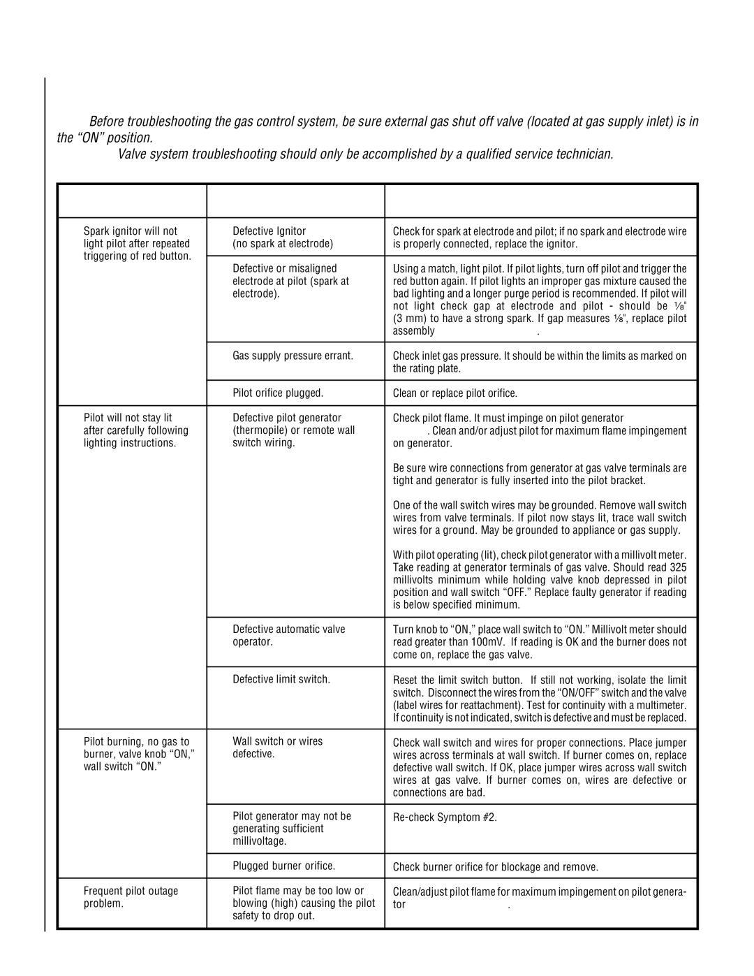
TROUBLESHOOTING THE MILLIVOLT GAS CONTROL SYSTEM
Note: Before troubleshooting the gas control system, be sure external gas shut off valve (located at gas supply inlet) is in the “ON” position.
Important: Valve system troubleshooting should only be accomplished by a qualified service technician.
| SYMPTOM | POSSIBLE CAUSES | CORRECTIVE ACTION | |
|
|
|
|
|
1. | Spark ignitor will not | A. Defective Ignitor | Check for spark at electrode and pilot; if no spark and electrode wire | |
| light pilot after repeated | (no spark at electrode) | is properly connected, replace the ignitor. | |
| triggering of red button. |
|
|
|
|
| B. Defective or misaligned | Using a match, light pilot. If pilot lights, turn off pilot and trigger the | |
|
|
| ||
|
|
| electrode at pilot (spark at | red button again. If pilot lights an improper gas mixture caused the |
|
|
| electrode). | bad lighting and a longer purge period is recommended. If pilot will |
|
|
|
| not light check gap at electrode and pilot - should be ¹⁄₈" |
|
|
|
| (3 mm) to have a strong spark. If gap measures ¹⁄₈", replace pilot |
|
|
|
| assembly (Figure 11 on page 7). |
|
|
|
|
|
|
|
| C. Gas supply pressure errant. | Check inlet gas pressure. It should be within the limits as marked on |
|
|
|
| the rating plate. |
|
|
|
|
|
|
|
| D. Pilot orifice plugged. | Clean or replace pilot orifice. |
|
|
|
| |
2. | Pilot will not stay lit | A. Defective pilot generator | Check pilot flame. It must impinge on pilot generator (Figure 11 on | |
| after carefully following | (thermopile) or remote wall | page 7). Clean and/or adjust pilot for maximum flame impingement | |
| lighting instructions. | switch wiring. | on generator. | |
|
|
|
| Be sure wire connections from generator at gas valve terminals are |
|
|
|
| tight and generator is fully inserted into the pilot bracket. |
|
|
|
| One of the wall switch wires may be grounded. Remove wall switch |
|
|
|
| wires from valve terminals. If pilot now stays lit, trace wall switch |
|
|
|
| wires for a ground. May be grounded to appliance or gas supply. |
|
|
|
| With pilot operating (lit), check pilot generator with a millivolt meter. |
|
|
|
| Take reading at generator terminals of gas valve. Should read 325 |
|
|
|
| millivolts minimum while holding valve knob depressed in pilot |
|
|
|
| position and wall switch “OFF.” Replace faulty generator if reading |
|
|
|
| is below specified minimum. |
|
|
|
|
|
|
|
| B. Defective automatic valve | Turn knob to “ON,” place wall switch to “ON.” Millivolt meter should |
|
|
| operator. | read greater than 100mV. If reading is OK and the burner does not |
|
|
|
| come on, replace the gas valve. |
|
|
|
|
|
|
|
| C. Defective limit switch. | Reset the limit switch button. If still not working, isolate the limit |
|
|
|
| switch. Disconnect the wires from the “ON/OFF” switch and the valve |
|
|
|
| (label wires for reattachment). Test for continuity with a multimeter. |
|
|
|
| If continuity is not indicated, switch is defective and must be replaced. |
|
|
|
| |
3. | Pilot burning, no gas to | A. Wall switch or wires | Check wall switch and wires for proper connections. Place jumper | |
| burner, valve knob “ON,” | defective. | wires across terminals at wall switch. If burner comes on, replace | |
| wall switch “ON.” |
| defective wall switch. If OK, place jumper wires across wall switch | |
|
|
|
| wires at gas valve. If burner comes on, wires are defective or |
|
|
|
| connections are bad. |
|
|
|
|
|
|
|
| B. Pilot generator may not be | |
|
|
| generating sufficient |
|
|
|
| millivoltage. |
|
|
|
|
|
|
|
|
| C. Plugged burner orifice. | Check burner orifice for blockage and remove. |
|
|
|
| |
4. | Frequent pilot outage | A. Pilot flame may be too low or | Clean/adjust pilot flame for maximum impingement on pilot genera- | |
| problem. | blowing (high) causing the pilot | tor (Figure 11 on page 7). | |
|
|
| safety to drop out. |
|
|
|
|
|
|
