4
CONTROL KNOB |
MILLIVOLT GAS CONTROL VALVE |
Figure 3 |
Operation of millivolt and electronic gas con- trol systems are different. Before lighting and operating your appliance determine if you have a millivolt or electronic appliance. Millivolt appliances will be fitted with the gas control valve shown in Figure 3. Appliances with electronic systems will be fitted with the elec- tronic valve shown in Figure 4. Familiarize yourself with the differing controls for the valve your appliance uses.
Millivolt Appliance Lighting
To light millivolt appliances refer to the de- tailed lighting instructions found in both En- glish and French on pages 10 and 11 of these instructions respectively. Appliance lighting instructions may also be found on the pull- out label located near the gas valve in the control compartment. Refer to Figure 1 for the piezo ignitor location used with your appliance.
Your appliance comes supplied with remote wall switch or can be used with an optional remote control kit. The appliance main burner may be turned on and off with the wall switch or remote control.
Electronic Appliance Lighting
To light electronic appliances refer to the de- tailed lighting instructions found in both En- glish and French on pages 12 and 13 of these instructions respectively. Appliance lighting instructions may also be found on the pull- out label located near the gas valve in the control compartment.
Your appliance comes supplied with remote wall switch or can be used with an optional remote control kit. The appliance main burner may be turned on and off with the wall switch or remote control.
1.When lit for the first time, this appliance will emit a slight odor for an hour or two. This is due to the
ON/OFF SWITCH
O N | O F F |
P
C
M
ELECTRONIC GAS CONTROL VALVE
Figure 4
2.Keep lower control compartment clean by vacuuming or brushing at least twice a year. More frequent cleaning may be required due to excessive lint from carpeting, bedding ma- terials, etc. It is important that control com- partments, burners and circulating air pas- sageways of the appliance be kept clean.
3.Always turn off gas to the pilot (millivolt appliances) before cleaning. Before
Appliance lighting instructions may also be found on the
4.Always keep the appliance area clear and free from combustible materials, gasoline and other flammable liquids.
5.Remember, Millivolt appliances have a con- tinuous burning pilot flame. Exercise caution when using products with combustible vapors.
6.Clean the optional glass doors only when necessary. Wipe surface with clean, damp- ened, soft cloth. Follow with dry, soft towel as desired. Take care not to scratch the glass surface.
WARNING: DO NOT USE ABRASIVE CLEANERS. NEVER CLEAN THE GLASS WHEN IT IS HOT.
CAUTION: DO NOT ATTEMPT TO TOUCH THE DOORS WITH YOUR HANDS WHILE THE FIRE- PLACE IS IN USE. ALWAYS USE DOOR HANDLES. DOORS WILL BECOME VERY HOT WHEN FIREPLACE IS IN USE.
WARNING: FIREPLACES EQUIPPED WITH OPTIONAL ACCESSORY DOORS SHOULD BE OPERATED ONLY WITH THE DOORS FULLY OPEN OR FULLY CLOSED (FIGURE 5 ). THIS APPLIANCE MAY
ONLY BE FITTED WITH DOORS CERTI- FIED FOR USE WITH THE APPLIANCE.
NOTE: DIAGRAMS & ILLUSTRATIONS NOT TO SCALE.
AVERTISSEMENT: POUR UTILISATION UNIQUEMENT AVEC LES PORTES EN VERRE CERTIFIÊES AVEC L'APPAREIL.
Glass Doors |
Fully Open or |
Fully Closed |
Figure 5 |
Outside Combustion Air Controls
Appliances may be installed with an outside
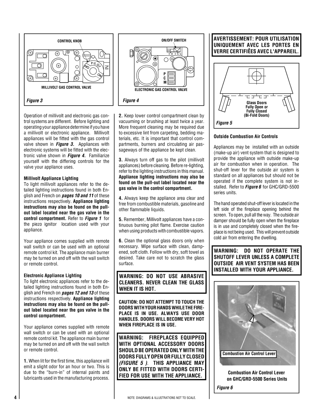
The hand operated
WARNING: DO NOT OPERATE THE SHUTOFF LEVER UNLESS A COMPLETE OUTSIDE AIR VENT SYSTEM HAS BEEN INSTALLED WITH YOUR APPLIANCE.
Combustion Air Control Lever
Combustion Air Control Lever on
Figure 6