Additional Sample Schematics
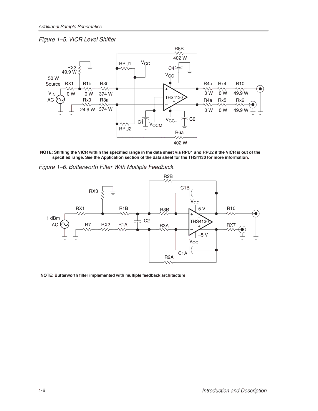
Figure 1±5. VICR Level Shifter |
|
|
|
| |||
|
|
|
|
|
| R6B |
|
|
|
| RPU1 | VCC | 402 Ω |
| |
| RX3 |
| C4 |
| |||
| 49.9 Ω |
|
|
|
| VCC |
|
50 Ω |
|
|
|
|
|
| |
RX1 | R1b | R3b |
|
|
| R4b | |
Source |
|
| + | ||||
|
|
|
|
|
|
| |
VIN | 0 Ω | 0 Ω | 374 Ω |
|
| ± | 0 Ω |
|
| THS4130 | |||||
AC |
| Rx0 | R3a |
|
| R4a | |
|
|
| + | ||||
|
| 24.9 Ω | 374 Ω |
|
| ± |
|
|
|
|
|
| 0 Ω | ||
|
|
|
| C1 | VOCM | VCC± | C6 |
|
|
| RPU2 |
|
|
| |
|
|
|
|
| R6a |
| |
|
|
|
|
|
|
| |
|
|
|
|
|
| 402 Ω |
|
Rx4 | R10 |
0 Ω | 49.9 Ω |
Rx5 | Rx6 |
0 Ω | 49.9 Ω |
NOTE: Shifting the VICR within the specified range in the data sheet via RPU1 and RPU2 if the VICR is out of the specified range. See the Application section of the data sheet for the THS4130 for more information.
Figure 1±6. Butterworth Filter With Multiple Feedback.
RX3
RX1R1B
1 dBm
AC | R7 | RX2 R1A |
R2B |
|
|
|
| C1B |
|
|
| VCC |
| |
R3B | + | 5 V | R10 |
| ± |
| |
C2 |
|
| |
THS4130 | RX7 | ||
R3A | ± | + | |
|
|
| |
|
| ±5 V |
|
| VCC± |
| |
R2A | C1A |
|
|
|
|
| |
NOTE: Butterworth filter implemented with multiple feedback architecture
Introduction and Description |