2.3Input and Output Setup
1)Ensure that JU3, JU4, and JU1 are not installed (open circuit).
2)Set the function generator to generate a 1 MHz, ±0.5 V (1 VPP) sine wave with no dc offset.
3)Turn off the function generator before proceeding to the next step.
4)Using a
5)Using a
6)Using a
Note: The oscilloscope must be set to use a
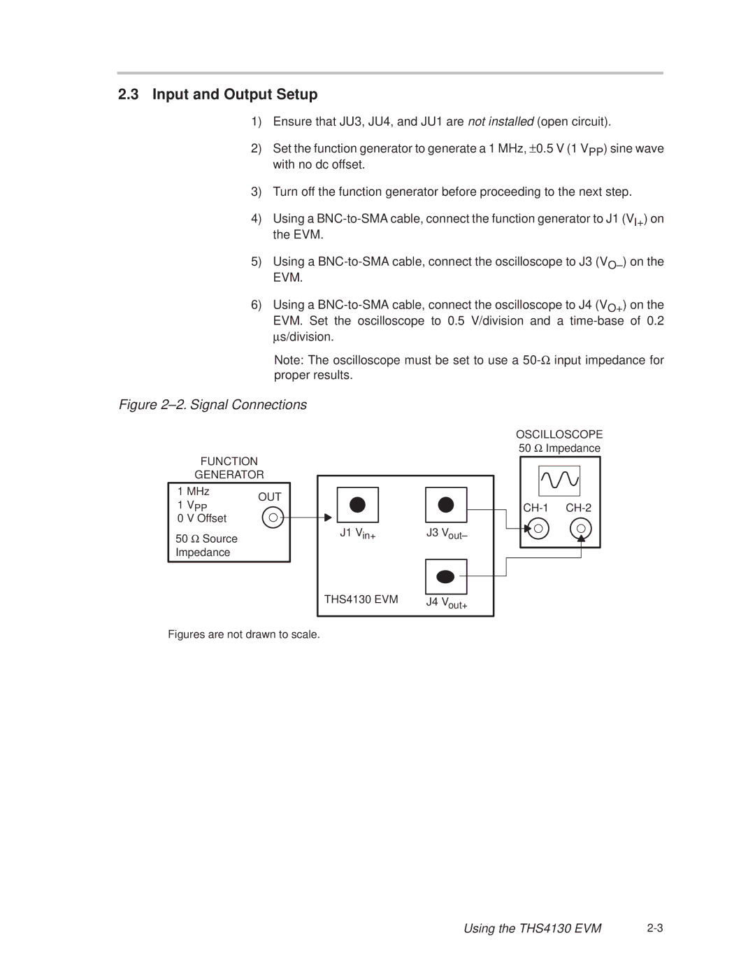
Figure 2±2. Signal Connections
FUNCTION
GENERATOR
1 MHz | OUT |
| |
1 VPP |
| ||
|
|
| |
0 V Offset |
|
|
|
|
|
| |
50 Ω Source |
|
|
|
Impedance |
|
|
|
|
|
|
|
J1 Vin+ | J3 Vout± |
OSCILLOSCOPE 50 Ω Impedance
THS4130 EVM | J4 Vout+ |
Figures are not drawn to scale.
Using the THS4130 EVM |