TOSHIBA 4200FA UPS
Installation Planning Guide for 15-80kVA UPS
Standard System: 208/120V Input, 208/120V Output
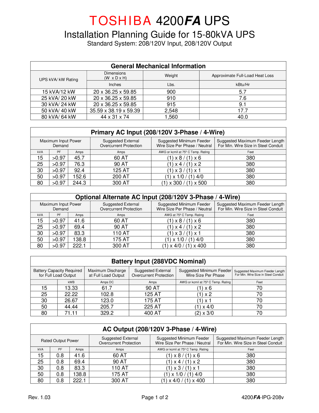
General Mechanical Information
|
|
|
| Dimensions |
|
| Weight |
|
| Approximate |
|
| UPS kVA/ kW Rating |
|
| (W x D x H) |
|
|
|
|
| ||
|
|
|
|
|
|
|
|
|
| ||
|
|
| Inches |
|
| Lbs. |
|
| kBtu/Hr |
| |
|
|
|
|
|
|
|
|
| |||
| 15 kVA/12 kW |
| 20 x 36.25 x 59.85 | 900 |
| 5.7 |
| ||||
| 25 kVA/ 20 kW |
| 20 x 36.25 x 59.85 | 910 |
| 7.6 |
| ||||
| 30 kVA/ 24 kW |
| 20 x 36.25 x 59.85 | 915 |
| 9.1 |
| ||||
| 50 kVA/ 40 kW |
| 35.59 x 38.19 x 59.39 | 2,548 |
| 17.7 |
| ||||
| 80 kVA/ 64 kW |
| 44 x 31 x 74 | 1,560 |
| 40.0 |
| ||||
Primary AC Input (208/120V 3-Phase / 4-Wire)
Maximum Input Power | Suggested External | Suggested Minimum Feeder | Suggested Maximum Feeder Length | ||||
| Demand |
| Overcurrent Protection | Wire Size Per Phase / Neutral | For Min. Wire Size in Steel Conduit | ||
kVA | PF |
| Amps | Amps | AWG or kcmil at 75º C Temp. Rating | Feet | |
15 | >0.97 |
| 45.7 | 60 AT | (1) x 8 | / (1) x 6 | 380 |
25 | >0.97 |
| 76.3 | 90 AT | (1) x 4 | / (1) x 2 | 380 |
30 | >0.97 |
| 92.4 | 125 AT | (1) x 3 | / (1) x 1 | 380 |
50 | >0.97 |
| 152.6 | 200 AT | (1) x 1/0 / (1) 4/0 | 380 | |
80 | >0.97 |
| 244.3 | 300 AT | (1) x 300 | / (1) x 500 | 380 |
Optional Alternate AC Input (208/120V 3-Phase / 4-Wire)
Maximum Input Power | Suggested External | Suggested Minimum Feeder | Suggested Maximum Feeder Length | |||
| Demand |
| Overcurrent Protection | Wire Size Per Phase / Neutral | For Min. Wire Size in Steel Conduit | |
kVA | PF |
| Amps | Amps | AWG at 75º C Temp. Rating | Feet |
15 | >0.97 |
| 41.6 | 60 AT | (1) x 8 / (1) x 6 | 380 |
25 | >0.97 |
| 69.4 | 90 AT | (1) x 4 / (1) x 2 | 380 |
30 | >0.97 |
| 83.3 | 110 AT | (1) x 3 / (1) x 1 | 380 |
50 | >0.97 |
| 138.8 | 175 AT | (1) x 1/0 / (1) 4/0 | 380 |
80 | >0.97 |
| 222.1 | 300 AT | (1) x 4/0 / (1) x 400 | 380 |
Battery Input (288VDC Nominal)
|
|
|
|
|
|
|
|
|
Battery Capacity Required |
| Maximum Discharge |
| Suggested External |
| Suggested Minimum Feeder |
| |
for Full Load Output |
| at Full Load Output |
| Overcurrent Protection |
| Wire Size Per Phase |
| |
|
|
|
|
|
|
|
|
|
| kWB |
| Amps DC |
| Amps |
|
|
|
|
|
|
| AWG or kcmil at 75º C Temp. Rating | ||||
15 | 13.33 | 61.7 |
| 90 AT |
| (1) x 6 | ||
25 | 22.22 | 102.8 |
| 125 AT |
| (1) x 2 | ||
30 | 26.67 | 123.0 |
| 175 AT |
| (1) x 1 | ||
50 | 44.44 | 205.7 |
| 225 AT |
| (1) x 4/0 | ||
80 | 71.11 | 329.2 |
| 400 AT |
| (2) x 3/0 | ||
Suggested Maximum Feeder Length For Min. Wire Size in Steel Conduit
Feet
70
70
70
70
70
AC Output (208/120V 3-Phase / 4-Wire)
| Rated Output Power |
|
| Suggested External |
|
| Suggested Minimum Feeder |
|
| Suggested Maximum Feeder Length |
| ||
|
|
| Overcurrent Protection |
|
| Wire Size Per Phase / Neutral |
|
| For Min. Wire Size in Steel Conduit |
| |||
|
|
|
|
|
|
|
|
|
|
| |||
| kVA | PF | Amps |
|
| Amps |
|
| AWG or kcmil at 75º C Temp. Rating |
|
| Feet |
|
15 | 0.8 | 41.6 |
|
| 60 AT |
| (1) x 8 / (1) x 6 | 380 |
| ||||
25 | 0.8 | 69.4 |
|
| 90 AT |
| (1) x 4 / (1) x 2 | 380 |
| ||||
30 | 0.8 | 83.3 |
|
| 110 AT |
| (1) x 3 / (1) x 1 | 380 |
| ||||
50 | 0.8 | 138.8 |
|
| 175 AT |
| (1) x 1/0 / (1) 4/0 | 380 |
| ||||
80 | 0.8 | 222.1 |
|
| 300 AT |
| (1) x 4/0 / (1) x 400 | 380 |
| ||||
Rev. 1.03 | Page 1 of 2 |
