51HX93 57HX93 65HX93
It Makes a Difference Where Your TV Stands
Safety Precautions
Issue
Tune Into Safety
Installation, Care, and Service
Important Safety Instructions
Or continuous, unplug the power cord
When the unit is being turned on or
Contact a Toshiba Authorized Service Center
TV, follow these recommendations and precautions
Contents
Contents
Welcome to Toshiba
Features of your new TV
Introduction
Demo
TV back panel
4 5 6 7 8
Connecting your TV
TV front panel controls and connections
For an explanation of cable types, see
TV back panel connections
Overview of cable types
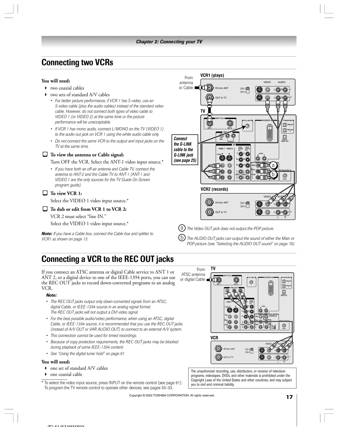
Two coaxial cables
You will need
To view the VCR
Video 1 or Video 2 at the same time or the picture
To view basic and premium Cable channels
Connecting a VCR and Cable box
Select the Video 1 video input source
Or the picture performance will be unacceptable
Select the ColorStream HD-1 video input source on the TV
Connecting a VCR and satellite receiver
To view the VCR or view and record antenna channels
Picture performance will be unacceptable
To view the DVD player
Connecting a DVD player with S-video and a VCR
To view premium Cable channels
To view antenna or Cable channels
Connecting a DVD player with component video and a VCR
To record a TV program while watching a DVD
From antenna or Cable
Connecting a VCR to the REC OUT jacks
Connecting two VCRs
Connecting a camcorder
Connecting a DVI/HDCP device
To view the camcorder video
Select the Video 3 video input source
Connecting an analog audio system
Connecting a digital audio system
Highlight Audio Setup and press Enter
One optical audio cable
System connection example
Connecting an A/V receiver
To control the devices
IEEE-1394 devices using On-screen control icons
To connect the IR blaster cable
Using analog-compatible IEEE-1394 devices
Connecting IEEE-1394 Firewire video devices
Supported signals
Using TheaterNet on-screen device control
To edit the IEEE-1394 device information
IEEE-1394 device initialization
IEEE-1394 device management
Chain connection
IEEE-1394 device interconnection
Hub connection
Hub connection
See
Link connection
To connect to the G-LINK jack
Channel Numbers 0-9, 100 directly access channels
Using the remote control
Learning about the remote control
Device mode control after programming
Installing the remote control batteries
To install the remote control batteries
Remote Control functional key chart
CBL/SAT Audio VCR CH RTN
Press Mode to select the TV mode to control the TV
Device code setup
Press Mode to select the mode you want to set up
Searching and sampling the code of a device
Operational feature reset
Using the volume lock feature
Repeatedly press Mode to select CABLE/SAT mode
To reset the volume controls to the original device mode
Cable boxes
Multi-brand remote control device codes
VCRs
Receivers
CD players
Cassette players
Laser disks
Main menu layout
Menu layout and navigation
Navigating the menu system
Setup / Installation menu layout
Press Menu to open the menu system
To close a menu instantly, press Exit
Manually starting the Quick Connect Guide assisted setup
Starting the Quick Connect Guide assisted setup
If you already set up the TV Guide On Screen system, go to
Selecting the menu language
Configuring the location of your TV
Setting up the TV Guide On Screen system
Configuring your Cable setup
Following screen opens. Press Enter to continue
Configuring your VCR setup
Cable box code testing
Do you have a VCR? Select YES or NO, and then press
For G-LINK connection details, see
See Important final setup steps, next
VCR code testing
Confirming your settings
Important final setup steps
Completing the Quick Connect Guide assisted setup
Configuring the antenna input sources
Setting up your TV
To configure the ANT 1 and ANT 2 input sources
Selecting the menu language
To program channels automatically
Programming channels into the TV’s channel memory
Programming channels automatically
Manually adding and deleting channels in the channel memory
To add and delete channels in the Favorite Channels lists
Programming your favorite channels
To clear your favorite channel lists
To tune your favorite channels
Setting up TheaterNet
Setting up and using TheaterNet on-screen device control
To set up TheaterNet device control
TheaterNet Setup menu opens
To close the on-screen control icons
Using the TheaterNet control icons
Press Exit
To view another source
Amplifiers
TheaterNet IR device codes
Laser disk players
Miscellaneous audio devices
ADC
Video accessory Hdtv decoder Receivers
STS
Manually adjusting the color
Adjusting the color convergence
Automatically adjusting the color
Convergence using TouchFocus
Setting the time and date
Checking system status
Viewing the digital signal meter
Restore Factory Defaults
Skip these steps and go to the next
TV Guide On Screen system includes the following features
Panel ad Channel Blue and Green
About the TV Guide On Screen menus
Windows
Action buttons
Navigating the TV Guide On Screen system
Viewing program listings and descriptions
Listings menu
Info windows
Channel surfing
Setting programs as favorites
Direct tuning
Video Window
One-touch and VCR Plus+ recording
Sort menu
Using the Menu Bar to access other menus
Viewing panel ads and channel ads
To open the Sort menu
Change system settings
Setup menu
Review options change the auto display setting
Schedule menu
Messages menu
Troubleshooting
Promotions menu
Selecting the video input source to view
Using the TVÕs features
Using the digital tuner hold
To label the video input sources To clear the video labels
Labeling the video input sources
Tuning to the next programmed channel
Tuning channels
Switching between two channels using Channel Return
Using SpeedSurf to change to a specific programmed channel
Selecting the picture size
Press PIC Size on the remote control
Natural picture size
To select the picture size
Theater Wide 2 picture size
Theater Wide 1 picture size
Theater Wide 3 picture size
Full picture size
To set the scroll settings
Using the auto aspect ratio feature 480i signals only
To turn on the Auto Aspect feature
To turn off the Auto Aspect feature
To set the Cinema Mode to Film
Selecting the cinema mode
To set the Cinema Mode to Video
To select the display format
Using the POP double-window feature
Using the POP features
To display a program in the POP window
To close the POP window
Adjusting the size of the main and POP pictures
Switching the main and POP pictures
Freezing the main picture in the POP double-window
To close the still POP window
To cancel the channel scan without changing the channel
Using the programmed channel scan feature
POP double-window aspect ratio
To scan the programmed channels
To scan and tune your favorite channels
Using the favorite channel search feature
Selecting the picture mode
Adjusting the picture
Adjusting the picture quality
Resetting the picture settings
To deactivate the ALS
To turn on the flesh tone feature
To activate the ALS
Adjusting the velocity scan modulation
Using CableClear DNR digital noise reduction
Selecting the color temperature
Resetting the advanced picture settings
Advanced closed captions
Using the closed caption mode
Using the sub-bass system SBS
Adjusting the audio
Muting the sound
Selecting stereo/SAP broadcasts
Resetting your audio adjustments
Adjusting the audio quality
Using the StableSound feature
Using the Dolby Virtual SRS TruSurround sound feature
Using the SRS WOW surround sound feature
Resetting the advanced audio settings
Selecting the Audio OUT sound
Turning off the built-in speakers
Selecting the optical audio output format
Viewing digital photos on your TV
Using Memory card picture viewer
Memory card specifications
Memory card care and handling
Using the memory card picture viewer
During the slide show
To set the slide show interval
Setting the sleep timer
Setting the ON/OFF timer
Viewing the demo mode
Displaying TV setting information on-screen
Understanding the auto power off feature
Understanding the last mode memory feature
Entering the PIN code
Using the Locks menu
If you cannot remember your PIN code
Changing your PIN code
To block and unblock TV programs and movies
Blocking TV programs and movies by rating V-Chip
Press z to highlight Edit Rating Limits and press
Edit Rating Limits screen below appears
Locking video inputs
Blocking channels
Unlocking programs temporarily
Using the front panel lock feature
Using the game timer
Troubleshooting
¥ The sound may be muted. Press Volume
If Audio OUT is set to POP in the Audio Setup menu
Set to SAP mode
Restore Factory Defaults procedure as described on
Setup Questions
TV Guide On Screen FAQs
To hold detailed program descriptions for all of them
Operational Questions
How do I resize or close the Info window?
Edid = Enhanced-Extended Display Identification
Appendix
Limited United States Warranty
For additional information, visit TCL’s web site
Limited Canada Warranty
How to Obtain Warranty Services
51/57/65H93
51/57/65H93
Index
Picture adjustments
Channel programming
Picture-out-picture POP
Index
Remote control
03-08 RP
23566005