APPENDIX 1 SPECIFICATIONS | ENGLISH VERSION |
| A1.3 Media |
|
|
A1.3.4 Effective Print Area
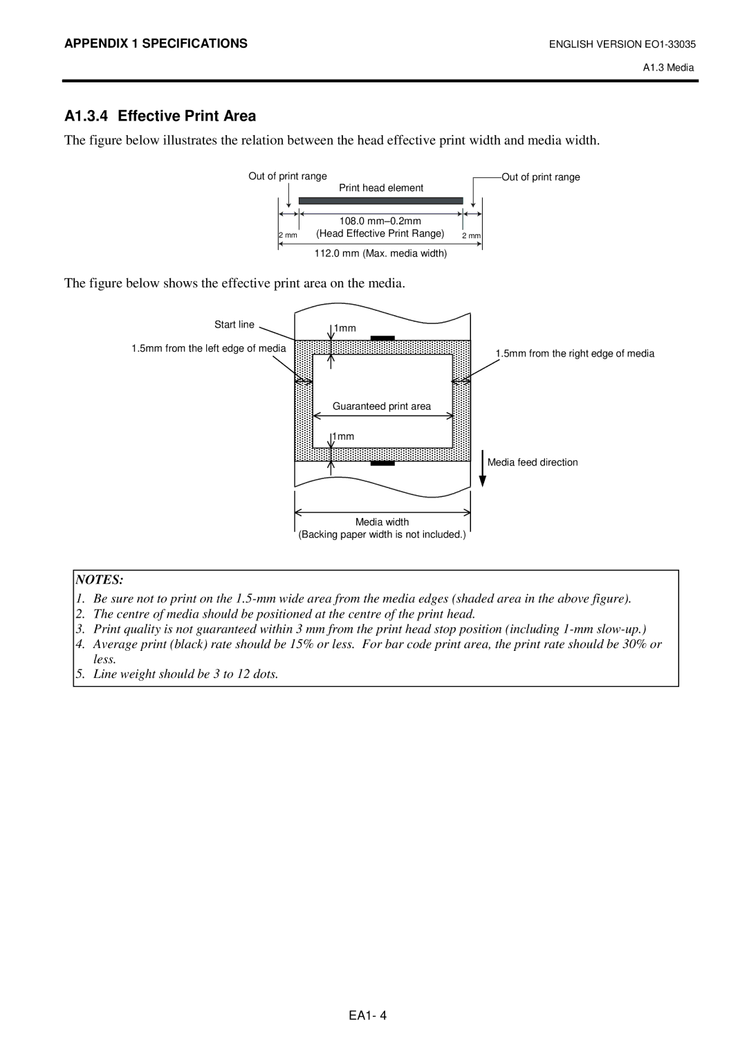
The figure below illustrates the relation between the head effective print width and media width.
Out of print range | Print head element |
|
|
|
|
| Out of print range | ||||
|
|
|
|
| |||||||
|
|
|
|
|
|
|
|
|
|
| |
|
|
|
|
|
|
|
|
|
|
|
|
|
|
|
|
|
|
|
|
|
|
|
|
|
|
|
|
|
|
|
|
|
|
|
|
|
|
|
|
|
|
|
|
|
|
|
|
|
|
|
|
| 108.0 mm±0.2mm |
|
|
|
|
|
|
2 mm | (Head Effective Print Range) | 2 mm | |||||||||
|
|
|
|
|
|
|
|
|
|
|
|
112.0 mm (Max. media width)
The figure below shows the effective print area on the media.
Start line
1.5mm from the left edge of media
1mm |
Guaranteed print area |
1mm |
1.5mm from the right edge of media
Media feed direction
Media width
(Backing paper width is not included.)
NOTES:
1.Be sure not to print on the
2.The centre of media should be positioned at the centre of the print head.
3.Print quality is not guaranteed within 3 mm from the print head stop position (including
4.Average print (black) rate should be 15% or less. For bar code print area, the print rate should be 30% or less.
5.Line weight should be 3 to 12 dots.
EA1- 4
