Battery pack | The rechargeable |
| provides power to the computer when the AC |
| adaptor is not connected. |
| For more detailed information on the use and |
| operation of the battery pack please refer to the |
| Battery section. |
|
|
Underside
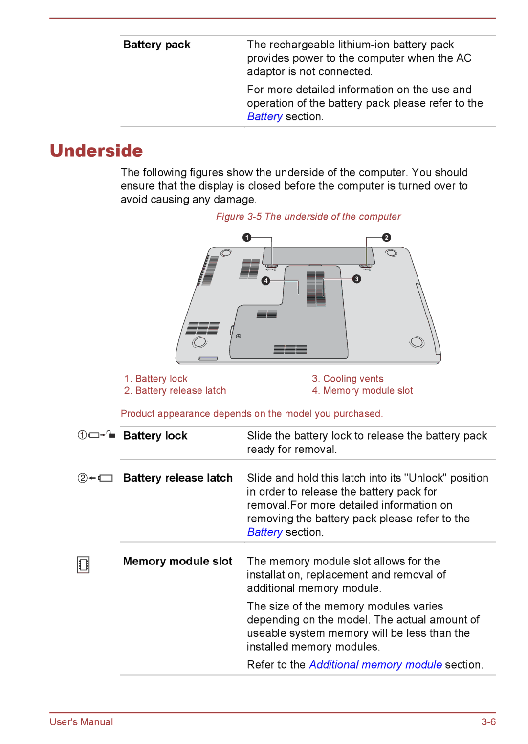
The following figures show the underside of the computer. You should ensure that the display is closed before the computer is turned over to avoid causing any damage.
Figure 3-5 The underside of the computer
1 | 2 |
4![]()
![]()
![]() 3
3
1. | Battery lock | 3. | Cooling vents |
2. | Battery release latch | 4. | Memory module slot |
Product appearance depends on the model you purchased.
Battery lock | Slide the battery lock to release the battery pack |
| ready for removal. |
|
|
Battery release latch | Slide and hold this latch into its "Unlock" position |
| in order to release the battery pack for |
| removal.For more detailed information on |
| removing the battery pack please refer to the |
| Battery section. |
Memory module slot | The memory module slot allows for the |
| installation, replacement and removal of |
| additional memory module. |
| The size of the memory modules varies |
| depending on the model. The actual amount of |
| useable system memory will be less than the |
| installed memory modules. |
| Refer to the Additional memory module section. |
|
|
User's Manual |