1. CD332 Overview
Status LEDs
Indicates the input signal ON/OFF status (DATA 0 - 7) and the interrupt generation point (STATUS 0 - 7). Normally STATUS 0 - 7 are all OFF. (momentary ON)
DATA 0 - 7 | Indicates the input signal status of IN0 to IN7. Lit when ON. |
STATUS 0 - 7 | Indicates the input point which is the interrupt factor. |
| (returned to OFF by resetting the interrupt flag) |
Interrupt timing setting DIP switches
Total 16 switches are provided. These switches are used to set the interrupt generation timing for each input point. (Rising, falling or both edges)
Refer to section 3.2.
Input terminals
Used to connect the external input signals. Refer to section 2.4.
NOTE
Do not connect any wires to the NC terminals.
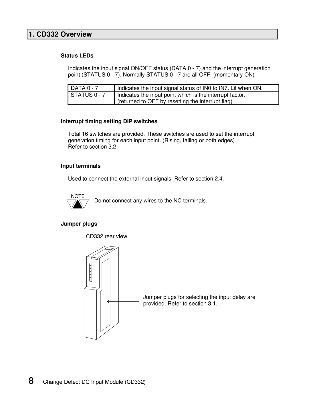
Jumper plugs
CD332 rear view
Jumper plugs for selecting the input delay are provided. Refer to section 3.1.
8 Change Detect DC Input Module (CD332)