2. Specifications
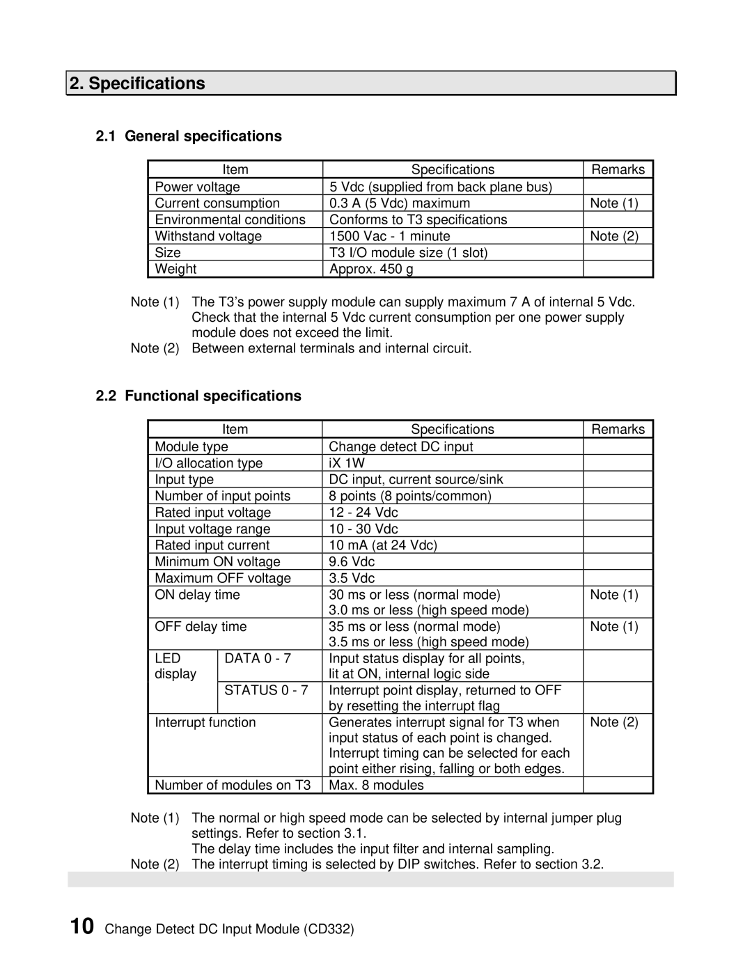
2.1 General specifications
Item | Specifications | Remarks |
Power voltage | 5 Vdc (supplied from back plane bus) |
|
Current consumption | 0.3 A (5 Vdc) maximum | Note (1) |
Environmental conditions | Conforms to T3 specifications |
|
Withstand voltage | 1500 Vac - 1 minute | Note (2) |
Size | T3 I/O module size (1 slot) |
|
Weight | Approx. 450 g |
|
Note (1) The T3’s power supply module can supply maximum 7 A of internal 5 Vdc. Check that the internal 5 Vdc current consumption per one power supply module does not exceed the limit.
Note (2) Between external terminals and internal circuit.
2.2 Functional specifications
| Item | Specifications | Remarks |
Module type | Change detect DC input |
| |
I/O allocation type | iX 1W |
| |
Input type |
| DC input, current source/sink |
|
Number of input points | 8 points (8 points/common) |
| |
Rated input voltage | 12 - 24 Vdc |
| |
Input voltage range | 10 - 30 Vdc |
| |
Rated input current | 10 mA (at 24 Vdc) |
| |
Minimum ON voltage | 9.6 Vdc |
| |
Maximum OFF voltage | 3.5 Vdc |
| |
ON delay time | 30 ms or less (normal mode) | Note (1) | |
|
| 3.0 ms or less (high speed mode) |
|
OFF delay time | 35 ms or less (normal mode) | Note (1) | |
|
| 3.5 ms or less (high speed mode) |
|
LED | DATA 0 - 7 | Input status display for all points, |
|
display |
| lit at ON, internal logic side |
|
| STATUS 0 - 7 | Interrupt point display, returned to OFF |
|
|
| by resetting the interrupt flag |
|
Interrupt | function | Generates interrupt signal for T3 when | Note (2) |
|
| input status of each point is changed. |
|
|
| Interrupt timing can be selected for each |
|
|
| point either rising, falling or both edges. |
|
Number of modules on T3 | Max. 8 modules |
| |
Note (1) The normal or high speed mode can be selected by internal jumper plug settings. Refer to section 3.1.
The delay time includes the input filter and internal sampling.
Note (2) The interrupt timing is selected by DIP switches. Refer to section 3.2.
10 Change Detect DC Input Module (CD332)