4. I/O Allocation
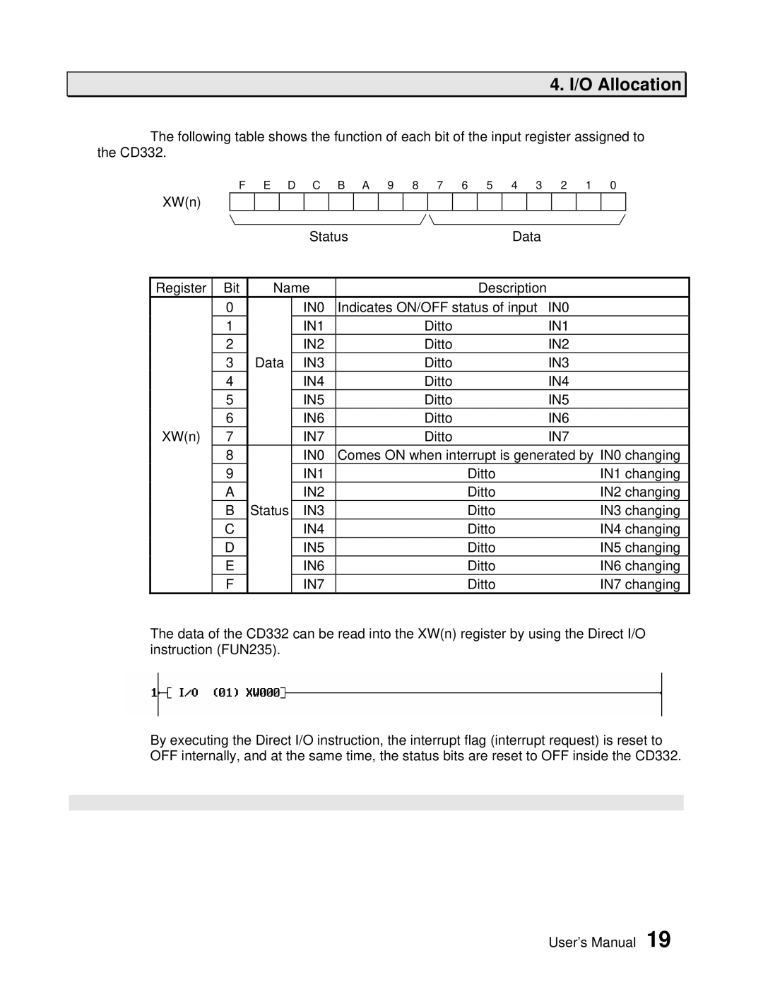
The following table shows the function of each bit of the input register assigned to the CD332.
F E D C B A 9 8 7 6 5 4 3 2 1 0
XW(n) |
|
|
|
|
|
|
|
|
|
|
|
|
|
|
|
|
|
|
|
|
|
|
|
|
|
|
|
|
| Status |
|
|
|
|
|
| Data |
|
|
|
|
| |||
|
|
|
|
|
|
|
|
|
|
|
|
|
|
|
|
|
| |||||
Register | Bit |
| Name |
|
|
|
|
|
|
| Description |
|
|
|
|
| ||||||
| 0 |
|
|
| IN0 |
| Indicates ON/OFF status of input | IN0 | ||||||||||||||
| 1 |
|
|
| IN1 |
|
|
|
| Ditto | IN1 | |||||||||||
| 2 |
|
|
| IN2 |
|
|
|
| Ditto | IN2 | |||||||||||
| 3 |
| Data | IN3 |
|
|
|
| Ditto | IN3 | ||||||||||||
| 4 |
|
|
| IN4 |
|
|
|
| Ditto | IN4 | |||||||||||
| 5 |
|
|
| IN5 |
|
|
|
| Ditto | IN5 | |||||||||||
| 6 |
|
|
| IN6 |
|
|
|
| Ditto | IN6 | |||||||||||
XW(n) | 7 |
|
|
| IN7 |
|
|
|
| Ditto | IN7 | |||||||||||
| 8 |
|
|
| IN0 |
| Comes ON when interrupt is generated by IN0 changing | |||||||||||||||
| 9 |
|
|
| IN1 |
|
|
|
|
|
| Ditto |
|
| IN1 changing | |||||||
| A |
|
|
| IN2 |
|
|
|
|
|
| Ditto |
|
| IN2 changing | |||||||
| B | Status | IN3 |
|
|
|
|
|
| Ditto |
|
| IN3 changing | |||||||||
| C |
|
|
| IN4 |
|
|
|
|
|
| Ditto |
|
| IN4 changing | |||||||
| D |
|
|
| IN5 |
|
|
|
|
|
| Ditto |
|
| IN5 changing | |||||||
| E |
|
|
| IN6 |
|
|
|
|
|
| Ditto |
|
| IN6 changing | |||||||
| F |
|
|
| IN7 |
|
|
|
|
|
| Ditto |
|
| IN7 changing | |||||||
The data of the CD332 can be read into the XW(n) register by using the Direct I/O instruction (FUN235).
By executing the Direct I/O instruction, the interrupt flag (interrupt request) is reset to OFF internally, and at the same time, the status bits are reset to OFF inside the CD332.
User’s Manual 19