Rear Side
4
2
ON
1![]()
3
75Ω HD/VD
EXT INT
OFF
SHT
TRG
P.S
M.G
VIDEO OUT | MIN | MAX |
DC IN/SYNC |
| M GAIN |
|
|
4
Enlarged
5
1 |
|
|
| O | ||
| ||||||
| ||||||
2 |
|
|
| N | ||
|
|
| ||||
3 |
|
| 1 |
| ||
|
| |||||
|
|
|
|
|
| |
4 |
|
|
|
|
|
|
|
|
|
|
|
| |
|
|
|
|
|
| |
5 |
|
|
|
|
|
|
|
|
|
|
|
| |
|
|
|
|
|
| |
6 |
|
|
|
|
|
|
|
|
|
| |||
|
|
| 2 |
| ||
7 |
|
|
|
|
|
|
|
|
|
|
|
| |
|
|
|
|
|
| |
8 |
|
|
|
|
|
|
|
|
|
|
|
| |
|
|
|
| 3 |
| |
|
|
| ||||
9 |
|
|
|
|
|
|
|
|
|
|
|
| |
|
|
|
|
|
| |
|
|
|
| 4 |
| |
|
|
| ||||
0 |
|
|
|
|
|
|
|
|
|
|
|
| |
|
|
|
| 5 |
| |
|
|
| ||||
|
| |||||
|
|
|
|
|
|
|
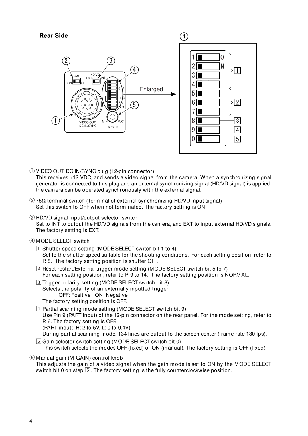
1VIDEO OUT DC IN/SYNC plug
This receives +12 VDC, and sends a video signal from the camera. When a synchronizing signal generator is connected to this plug and an external synchronizing signal (HD/VD signal) is applied, the camera can be operated synchronously with the external signal.
275Ω terminal switch (Terminal of external synchronizing HD/VD input signal) Set this switch to OFF when not terminated. The factory setting is ON.
3HD/VD signal input/output selector switch
Set to INT to output the HD/VD signals from the camera, and EXT to input external HD/VD signals. The factory setting is EXT.
4MODE SELECT switch
1Shutter speed setting (MODE SELECT switch bit 1 to 4)
Set to the shutter speed suitable for the shooting conditions. For each setting position, refer to
P.8. The factory setting position is shutter OFF.
2Reset restart/External trigger mode setting (MODE SELECT switch bit 5 to 7)
For each setting position, refer to P. 9 to 14. The factory setting position is NORMAL.
3Trigger polarity setting (MODE SELECT switch bit 8) Selects the polarity of an externally inputted trigger.
OFF: Positive ON: Negative The factory setting position is OFF.
4Partial scanning mode setting (MODE SELECT switch bit 9)
Use Pin 9 (PART input) of the
P.6. The factory setting is OFF.
(PART input; H: 2 to 5V, L: 0 to 0.4V)
During partial scanning mode, 134 lines are output to the screen center (frame rate 180 fps).
5Gain selector switch setting (MODE SELECT switch bit 0)
This switch selects the modes OFF (fixed) or ON (manual). The factory setting is OFF (fixed).
5Manual gain (M GAIN) control knob
This adjusts the gain of a video signal when the gain mode is set to ON by the MODE SELECT switch bit 0 on step 5 . The factory setting is the fully counterclockwise position.
4