5![]() 2 Caution on Connection
2 Caution on Connection
䊶Only use optional camera head model #
䊶When connecting the camera cables, be sure to turn off the camera control unit and any other equipment connected to it.
䊶For DC power supply connecting to DC IN 12V terminal, use UL listed and/or CSA approved ungrounded type AC adaptor with the specifications described below.
Power supply voltage | 䋺 | 12V DC | 10% |
Current rating | 䋺 | More than 1.5A | |
Ripple voltage | 䋺 | Less than 50mV | |
Connector | 䋺 | ||
|
| Pins 1, 2 | 䋺 12V |
|
| Pins 3, 4 | 䋺 GND |
䊶If the securing screw on the connector of the camera cable loosens, noise may appear on the screen. Be sure to tighten the connector completely.
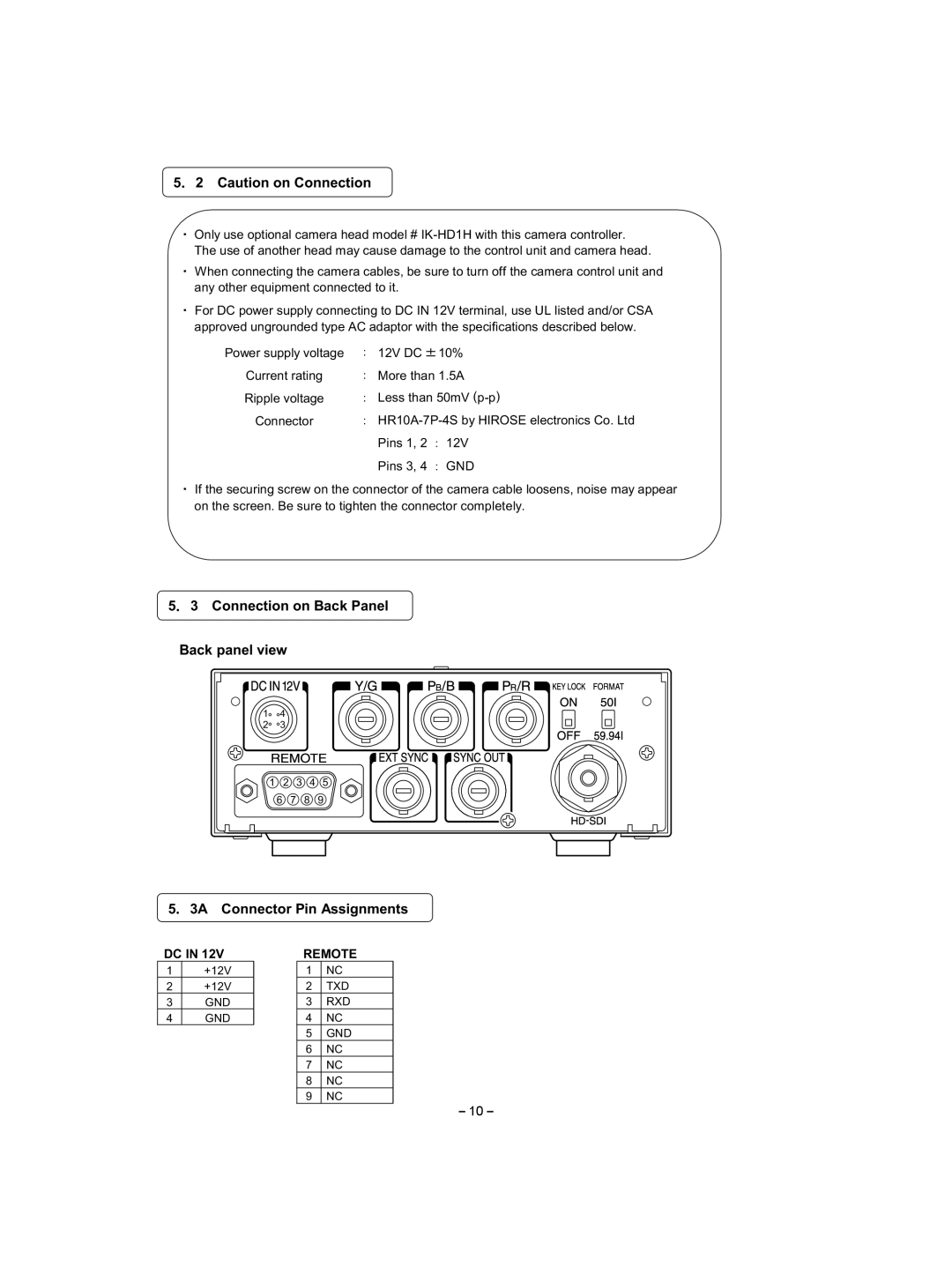
5 3 Connection on Back Panel
Back panel view
14
2 3
1 2 3 4 5
6 7 8 9
5 3A Connector Pin Assignments
DC IN 12V
1+12V
2+12V
3GND
4 GND
REMOTE
1NC
2 TXD
3 RXD
4 NC
5 GND
6 NC
7 NC
8 NC
9 NC
10