1.

COMPONENTS:


(1)

Camera

1


(2)

Accessories


(a) Lens Connector

1

(E4-191J-100(M))


(b) Instruction Manual

1


(c) Lens Cap

1


2. CONNECTION AND OPERATIONS

Notes on connecting

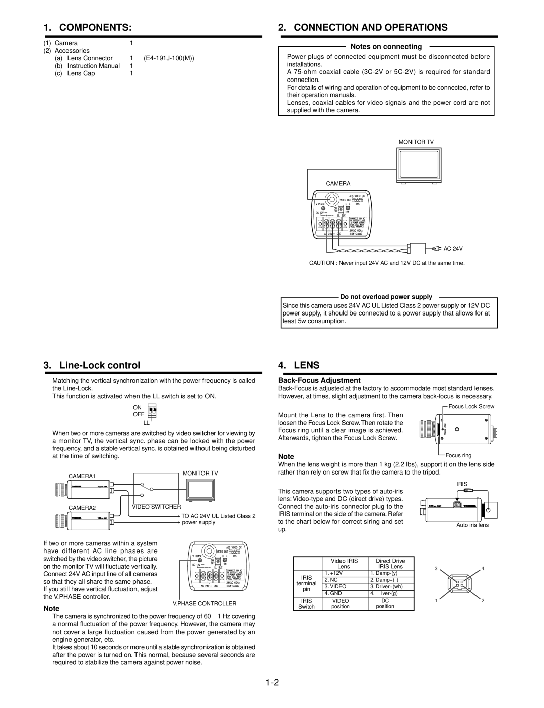
Power plugs of connected equipment must be disconnected before installations.

A75-ohm coaxial cable (3C-2V or 5C-2V) is required for standard connection.

For details of wiring and operation of equipment to be connected, refer to their operation manuals.

Lenses, coaxial cables for video signals and the power cord are not supplied with the camera.

MONITOR TV

CAMERA

AC 24V

CAUTION : Never input 24V AC and 12V DC at the same time.

Do not overload power supply

Since this camera uses 24V AC UL Listed Class 2 power supply or 12V DC power supply, it should be connected to a power supply that allows for at least 5w consumption.

3. Line-Lock control

Matching the vertical synchronization with the power frequency is called the Line-Lock.

This function is activated when the LL switch is set to ON.

ON

OFF

LL

When two or more cameras are switched by video switcher for viewing by a monitor TV, the vertical sync. phase can be locked with the power frequency, and a stable vertical sync. is obtained without being disturbed at the time of switching.

CAMERA1


MONITOR TV


4. LENS

Back-Focus Adjustment

Back-Focus is adjusted at the factory to accommodate most standard lenses. However, at times, slight adjustment to the camera back-focus is necessary.

Focus Lock Screw

Mount the Lens to the camera first. Then loosen the Focus Lock Screw. Then rotate the Focus ring until a clear image is achieved. Afterwards, tighten the Focus Lock Screw.

Note


Focus ring


When the lens weight is more than 1 kg (2.2 lbs), support it on the lens side rather than rely on screw that fix the camera to the tripod.

CAMERA2

VIDEO SWITCHER


TO AC 24V UL Listed Class 2


power supply

If two or more cameras within a system have different AC line phases are switched by the video switcher, the picture on the monitor TV will fluctuate vertically. Connect 24V AC input line of all cameras so that they all share the same phase.

If you still have vertical fluctuation, adjust the V.PHASE controller.

V.PHASE CONTROLLER

Note

The camera is synchronized to the power frequency of 60 1 Hz covering a normal fluctuation of the power frequency. However, the camera may not cover a large fluctuation caused from the power generated by an engine generator, etc.

It takes about 10 seconds or more until a stable synchronization is obtained after the power is turned on. This normal, because several seconds are required to stabilize the camera against power noise.

This camera supports two types of auto-iris lens: Video-type and DC (direct drive) types. Connect the auto-iris connector plug to the IRIS terminal on the side of the camera. Refer to the chart below for correct siring and set up.


Video IRIS

Direct Drive


Lens

IRIS Lens

IRIS

1. +12V

1. Damp-(y)

2. NC

2. Damp+( )

terminal

3. VIDEO

3. Driver+(wh)

pin

4. GND

4. iver-(g)


IRIS

VIDEO

DC

Switch

position

position

IRIS

Auto iris lens

1-2

Page 2
Image 2
Toshiba IK-6400A, Ik6200a, IK-6200A instruction manual Components, Connection and Operations, Lens, Back-Focus Adjustment

IK-6200A, IK-6400A, Ik6200a specifications

The Toshiba IK-6200A, IK-6400A, and IK-6100A are advanced imaging systems renowned for their high-quality performance and versatility in various applications, including industrial inspection, medical imaging, and security surveillance. These cameras leverage Toshiba's years of expertise in imaging technology to deliver exceptional results in demanding environments.

The IK-6200A and IK-6400A models are highlighted by their advanced signal processing capabilities, ensuring that they capture sharp, clear images even in low-light conditions. Both models utilize a 1/2-inch CCD (Charge-Coupled Device) sensor, which offers superior resolution and minimal noise, making them ideal for critical applications where detail is paramount. They are capable of achieving resolutions up to 640 x 480 pixels, providing high-quality images with excellent color fidelity.

One of the key features of the IK-6200A and IK-6400A is their dynamic range, allowing them to capture a wider range of luminance levels, which is crucial in situations where lighting conditions may fluctuate. The automatic gain control capability ensures optimal brightness levels without manual adjustments, enhancing user experience and efficiency.

The IK-6400A distinguishes itself with enhanced frame rates, making it suitable for dynamic environments where motion detection is essential. Users can benefit from its ability to capture moving objects with clarity, reducing motion blur and improving overall image quality. This feature is particularly valuable in security applications, where real-time monitoring is critical.

Both models showcase Toshiba's commitment to robust build quality and reliability. They are designed to endure harsh operating conditions, including exposure to dust, moisture, and varying temperatures. This durability ensures that these cameras remain functional in a wide range of environments, from factory floors to outdoor surveillance.

In terms of connectivity, the IK-6200A and IK-6400A support various output formats, including analog and digital signals, ensuring compatibility with a range of recording and monitoring systems. This versatility facilitates easy integration into existing setups, making these models popular choices among professionals across multiple industries.

Overall, the Toshiba IK-6200A, IK-6400A, and IK-6100A cameras combine cutting-edge technology with durable design, making them reliable solutions for anyone seeking high-performance imaging systems. Their ability to deliver consistent results in challenging conditions underscores Toshiba’s reputation as a leader in imaging technology.