■Piping Precautions
(1) Flange connection
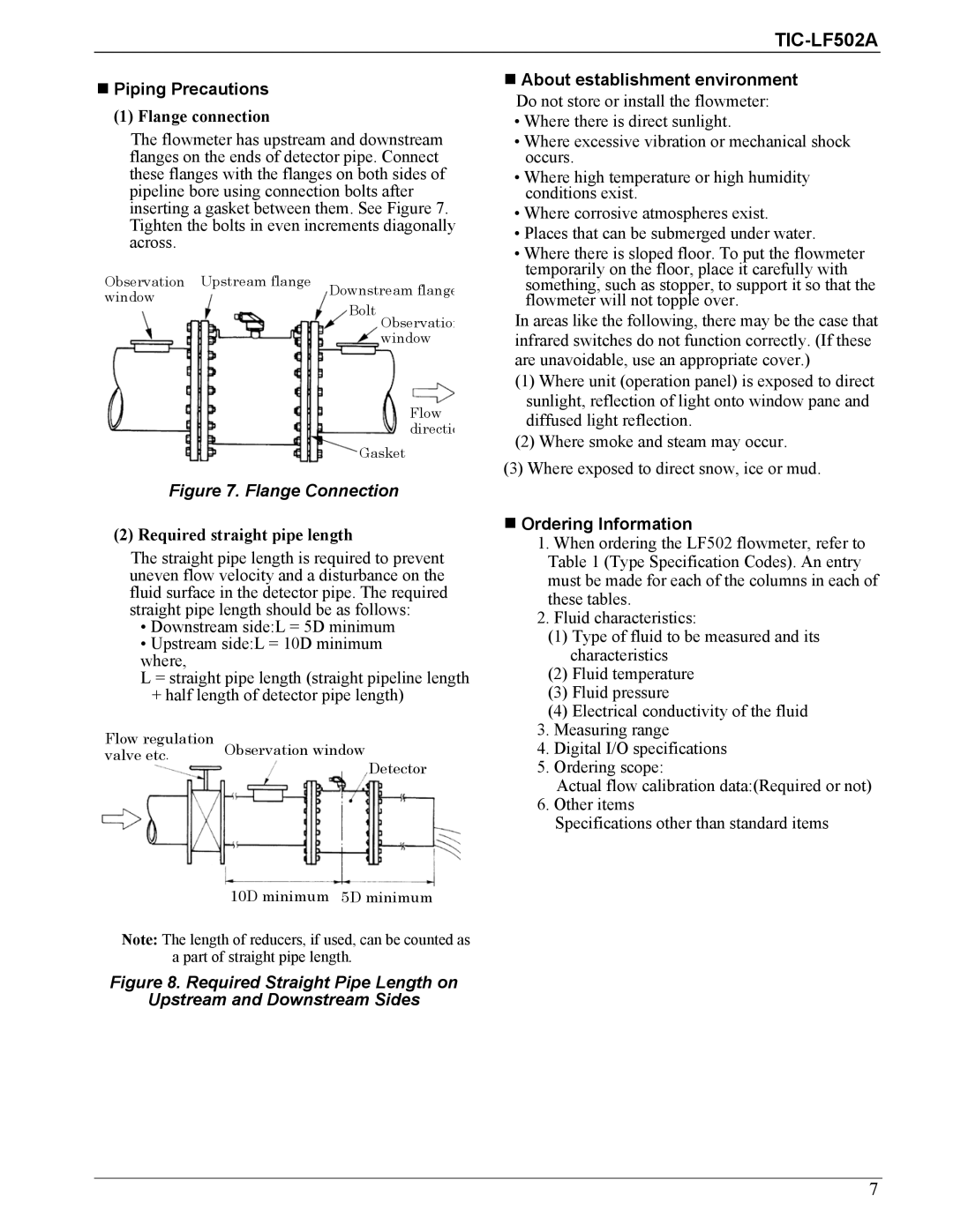
The flowmeter has upstream and downstream flanges on the ends of detector pipe. Connect these flanges with the flanges on both sides of pipeline bore using connection bolts after inserting a gasket between them. See Figure 7. Tighten the bolts in even increments diagonally across.
Observation Upstream flange Downstream flange window
Bolt Observatio window
Flow directio
Gasket
Figure 7. Flange Connection
(2) Required straight pipe length
The straight pipe length is required to prevent uneven flow velocity and a disturbance on the fluid surface in the detector pipe. The required straight pipe length should be as follows:
•Downstream side:L = 5D minimum
•Upstream side:L = 10D minimum where,
L = straight pipe length (straight pipeline length
+half length of detector pipe length)
Flow regulation | Observation window |
valve etc. | |
| Detector |
10D minimum 5D minimum
Note: The length of reducers, if used, can be counted as a part of straight pipe length.
Figure 8. Required Straight Pipe Length on
Upstream and Downstream Sides
■About establishment environment
Do not store or install the flowmeter:
•Where there is direct sunlight.
•Where excessive vibration or mechanical shock occurs.
•Where high temperature or high humidity conditions exist.
•Where corrosive atmospheres exist.
•Places that can be submerged under water.
•Where there is sloped floor. To put the flowmeter temporarily on the floor, place it carefully with something, such as stopper, to support it so that the flowmeter will not topple over.
In areas like the following, there may be the case that infrared switches do not function correctly. (If these are unavoidable, use an appropriate cover.)
(1)Where unit (operation panel) is exposed to direct sunlight, reflection of light onto window pane and diffused light reflection.
(2)Where smoke and steam may occur.
(3)Where exposed to direct snow, ice or mud.
■Ordering Information
1.When ordering the LF502 flowmeter, refer to Table 1 (Type Specification Codes). An entry must be made for each of the columns in each of these tables.
2.Fluid characteristics:
(1)Type of fluid to be measured and its characteristics
(2)Fluid temperature
(3)Fluid pressure
(4)Electrical conductivity of the fluid
3.Measuring range
4.Digital I/O specifications
5.Ordering scope:
Actual flow calibration data:(Required or not)
6.Other items
Specifications other than standard items
7
