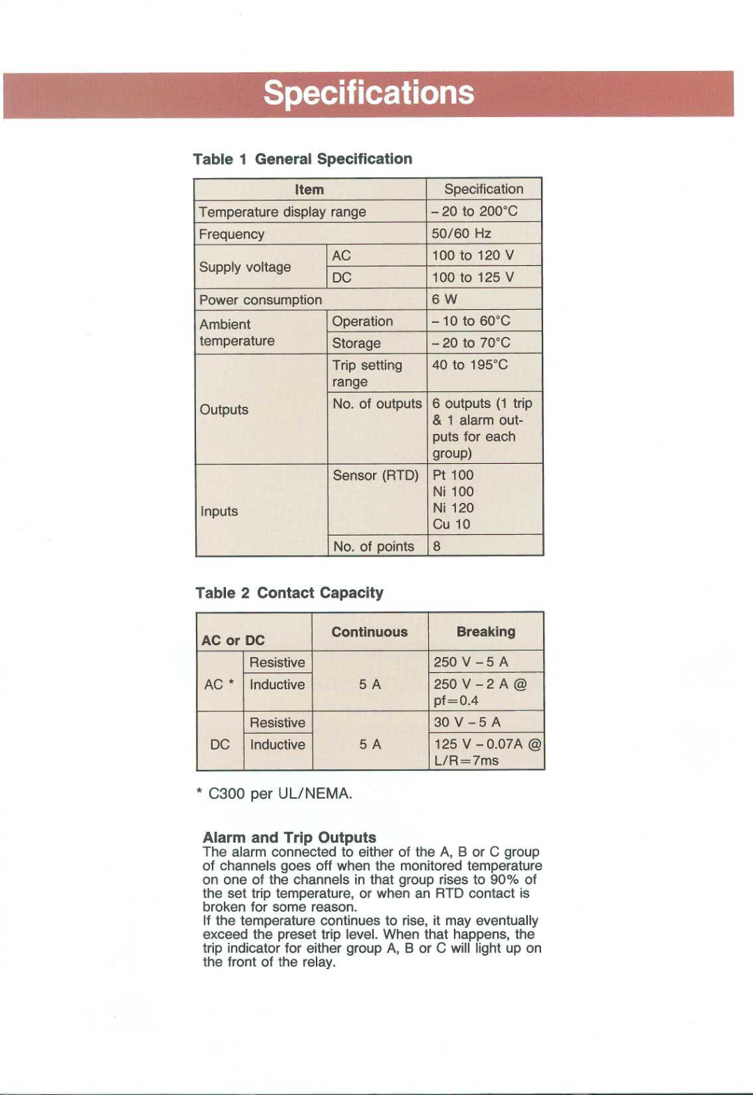
Table 1 General Specification
Item
Temperature display range
Frequency | AC | |
Supply voltage | ||
DC | ||
| ||
Power consumption |
| |
Ambient | Operation | |
temperature | Storage | |
| Trip setting | |
| range | |
Outputs | No. of outputs | |
| ||
| Sensor (RTD) | |
Inputs |
| |
| No. of points |
Specification
-20 to 200°C 50/60 Hz
100 to 120 V
100 to 125 V
6 W
-10 to 60°C
-20 to 70°C
40 to 195°C
6 outputs (1 trip
&1 alarm out- puts for each group)
Pt 100 Ni 100 Ni 120 Cu 10
8
Table 2 Contact Capacity |
|
| ||
AC or DC | Continuous |
| Breaking | |
|
|
| ||
| Resistive |
| 250 | V - 5 A |
AC * | Inductive | 5 A | 250 | V - 2 A @ |
|
|
| pf= | 0.4 |
| Resistive |
| 30 V - 5 A | |
DC | Inductive | 5 A | 125 | V |
|
|
| L/R=7ms | |
* C300 | per UL/NEMA. |
|
| |
Alarm and Trip Outputs
The alarm connected to either of the A, B or C group of channels goes off when the monitored temperature on one of the channels in that group rises to 90% of the set trip temperature, or when an RTD contact is broken for some reason.
If the temperature continues to rise, it may eventually exceed the preset trip level. When that happens, the trip indicator for either group A, B or C will light up on the front of the relay.