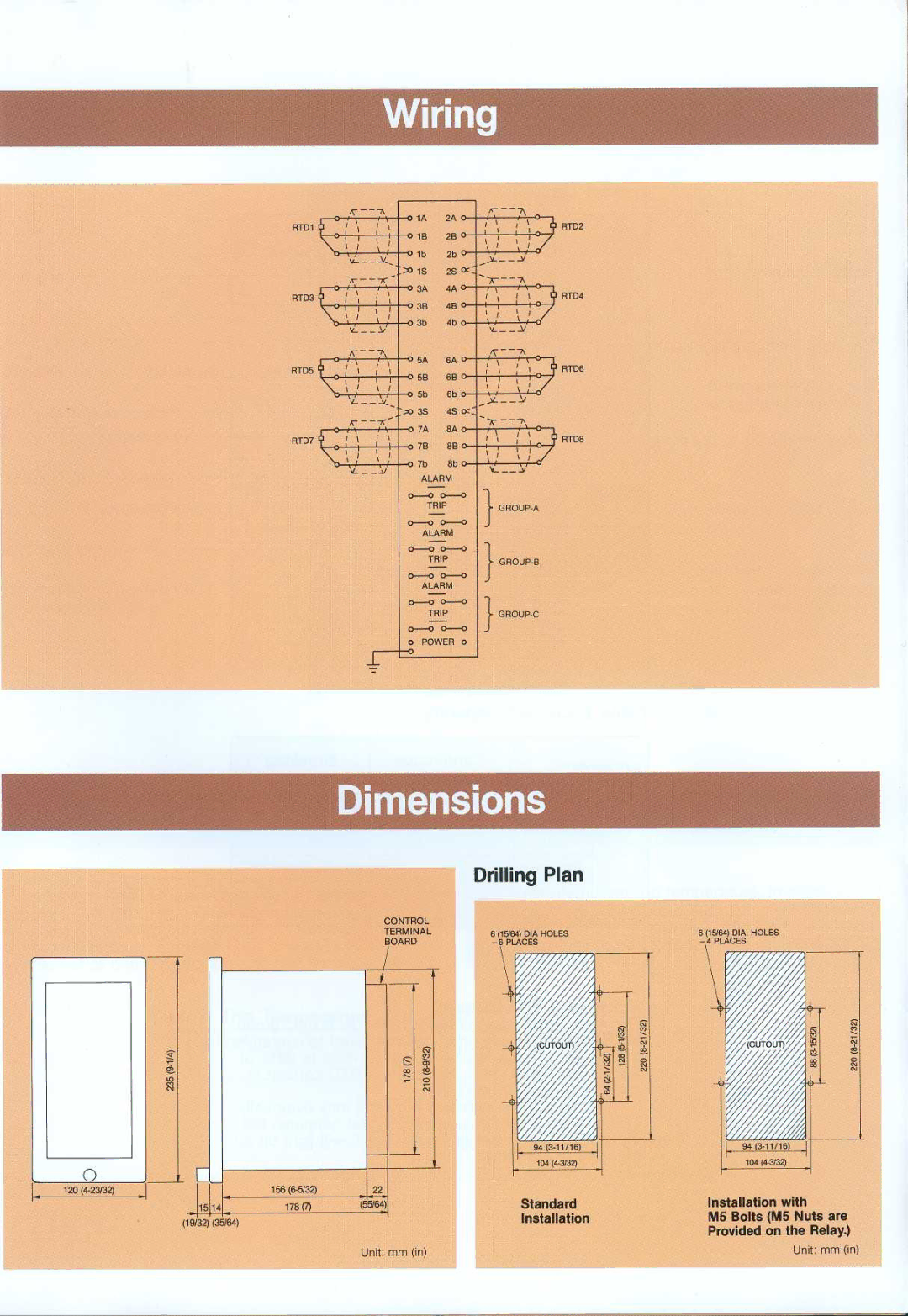
RTD1 | 2A |
| RTD2 | ||
| 2B |
| |||
|
|
|
| ||
| - ~1 b | 2b |
|
| |
| '~o 1S | 2S |
| ||
RTD3 | y 3A | 4A |
| RTD4 | |
4B |
| ||||
|
|
| |||
| 4- |
|
| ||
RTD5 | 6A |
| RTD6 | ||
^ ' 58 | 6B |
| |||
|
|
| |||
| Sb | 6b |
|
| |
| ;~o 3S | 4S |
|
| |
RTD7 | SA |
| RTDS | ||
SB | |||||
|
| ||||
| 7b | 8b | 0- |
|
ALARM
TRIPGROUP-A
ALARM
TRIPGROUP-B
ALARM
TRIPGROUP-C
O POWER o 0
| Drilling Plan |
CONTROL |
|
TERMINAL | 6 (Y5/64) DIA HOLES |
BOARD |
94
104
Standard
Installation
6 (15/64) DIA. HOLES
94
~
Installation with
M5 Bolts (M5 Nuts are Provided on the Relay.)
Unit : mm (in) | Unit : mm (in) |
