E 6 5 8 1 3 6 4
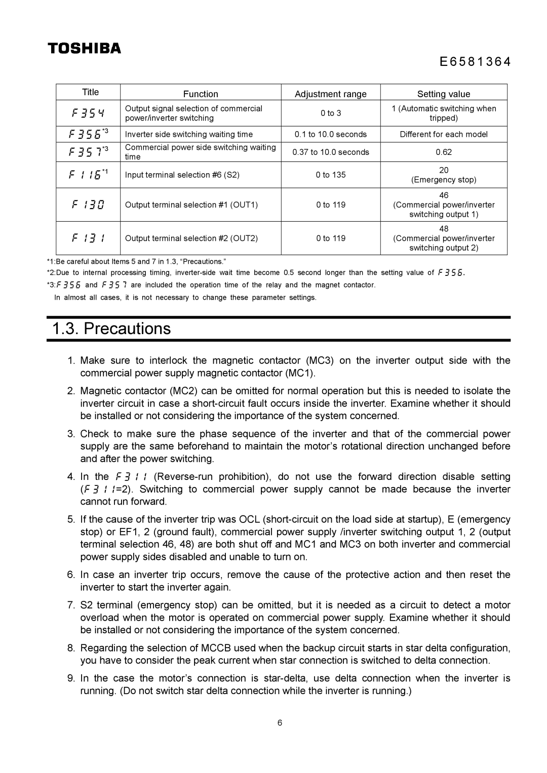
Title | Function | Adjustment range |
| Output signal selection of commercial | 0 to 3 |
| power/inverter switching |
|
*3 | Inverter side switching waiting time | 0.1 to 10.0 seconds |
*3 | Commercial power side switching waiting | 0.37 to 10.0 seconds |
| time |
|
*1 | Input terminal selection #6 (S2) | 0 to 135 |
|
|
|
| Output terminal selection #1 (OUT1) | 0 to 119 |
|
|
|
| Output terminal selection #2 (OUT2) | 0 to 119 |
|
|
|
Setting value
1 (Automatic switching when
tripped)
Different for each model
0.62
20
(Emergency stop)
46
(Commercial power/inverter
switching output 1)
48
(Commercial power/inverter
switching output 2)
*1:Be careful about Items 5 and 7 in 1.3, “Precautions.”
*2:Due to internal processing timing,
In almost all cases, it is not necessary to change these parameter settings.
1.3. Precautions
1.Make sure to interlock the magnetic contactor (MC3) on the inverter output side with the commercial power supply magnetic contactor (MC1).
2.Magnetic contactor (MC2) can be omitted for normal operation but this is needed to isolate the inverter circuit in case a
3.Check to make sure the phase sequence of the inverter and that of the commercial power supply are the same beforehand to maintain the motor’s rotational direction unchanged before and after the power switching.
4.In the
5.If the cause of the inverter trip was OCL
6.In case an inverter trip occurs, remove the cause of the protective action and then reset the inverter to start the inverter again.
7.S2 terminal (emergency stop) can be omitted, but it is needed as a circuit to detect a motor overload when the motor is operated on commercial power supply. Examine whether it should be installed or not considering the importance of the system concerned.
8.Regarding the selection of MCCB used when the backup circuit starts in star delta configuration, you have to consider the peak current when star connection is switched to delta connection.
9.In the case the motor’s connection is
6