E 6 5 8 1 3 6 4
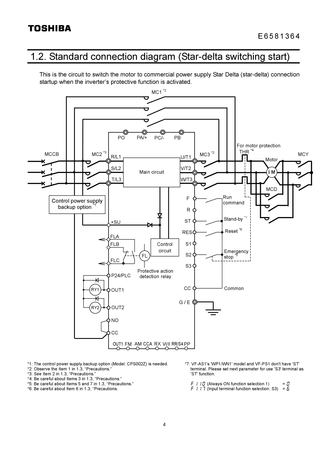
1.2. Standard connection diagram (Star-delta switching start)
This is the circuit to switch the motor to commercial power supply Star Delta
MC1 *2
|
| PO | PA/+ | PC/- | PB |
|
|
|
|
|
|
|
|
|
| For motor protection |
|
MCCB | MC2 | *3 |
|
| U/T1 | MC3 *2 | THR *4 | MCY |
|
| R/L1 |
|
|
| Motor |
| |
|
|
|
|
|
|
|
| |
|
| S/L2 | Main circuit | V/T2 |
| I M |
| |
|
|
|
|
|
| |||
|
| T/L3 |
|
| W/T3 |
|
|
|
|
|
|
|
|
|
| MCD |
|
Control power supply |
|
|
| F |
| Run |
| |
|
|
|
|
| command |
| ||
backup option *1 |
|
|
| R |
|
|
| |
|
|
|
|
|
|
|
| |
|
| +SU |
|
| ST |
|
| |
|
|
|
|
|
|
| ||
|
| FLA |
|
| RES |
| Reset *6 |
|
|
|
|
|
|
|
|
| |
|
| FLB |
| Control | S1 |
|
|
|
|
|
| FL | circuit | S2 |
| Emergency |
|
|
| FLC |
|
| stop *5 |
| ||
|
|
|
| S3 |
|
|
| |
|
|
| Protective action |
|
|
| ||
|
| P24/PLC |
|
|
|
| ||
|
| detection relay |
|
|
|
| ||
| RY1 | OUT1 |
|
| CC |
| Common |
|
|
|
|
|
|
|
| ||
| RY2 | OUT2 |
|
| G / E |
|
|
|
|
|
|
|
|
|
| ||
|
| NO |
|
|
|
|
|
|
|
| CC |
|
|
|
|
|
|
|
| OUT1 FM AM CCA RX VI/II RR/S4 PP |
|
|
| |||
*1: The control power supply backup option (Model: CPS002Z) is needed. | *7: | ||
*2: Observe the Item 1 in 1.3, “Precautions.” | terminal. Please set next parameter for use 'S3' terminal as | ||
*3: See Item 2 in 1.3, “Precautions.” | 'ST' function. |
| |
*4: Be careful about Items 3 in 1.3, “Precautions.” |
|
|
|
*5: Be careful about Items 5 and 7 in 1.3, “Precautions.” | f110 | (Always ON function selection 1) | = 0 |
*6: Be careful about Item 6 in 1.3, “Precautions. | f117 | (Input terminal function selection: S3) | = 6 |
4