E 6 5 8 1 3 6 4
2. Commercial Power Supply/Inverter Switching
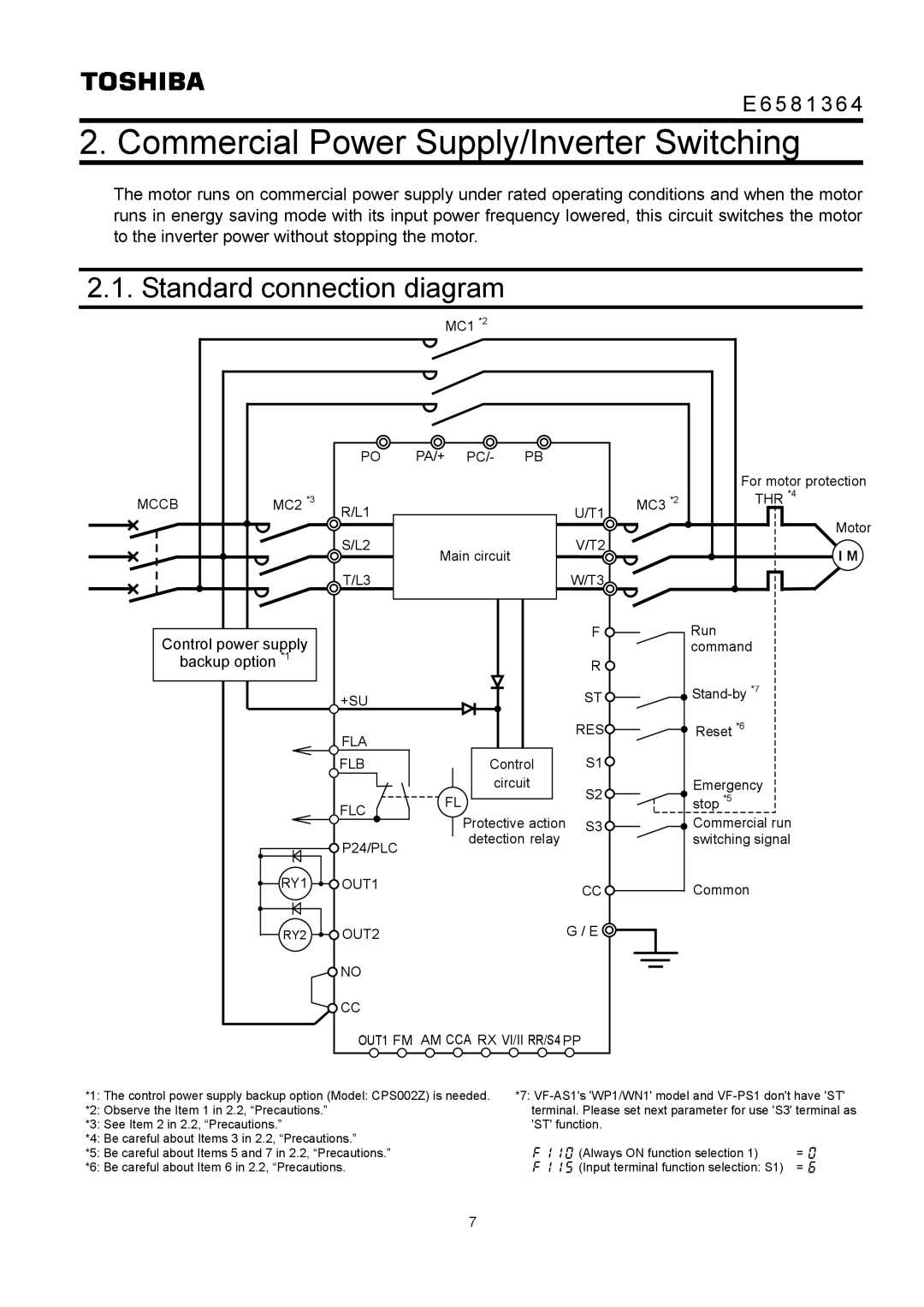
The motor runs on commercial power supply under rated operating conditions and when the motor runs in energy saving mode with its input power frequency lowered, this circuit switches the motor to the inverter power without stopping the motor.
2.1. Standard connection diagram |
|
|
|
| ||||
|
|
| MC1 *2 |
|
|
|
| |
|
| PO | PA/+ | PC/- | PB |
|
|
|
|
|
|
|
|
|
|
| For motor protection |
MCCB | MC2 | *3 |
|
|
| MC3 | *2 | THR *4 |
R/L1 |
|
| U/T1 |
|
| |||
|
|
|
|
|
| Motor | ||
|
| S/L2 |
|
| V/T2 |
|
| |
|
| Main circuit |
|
| I M | |||
|
|
|
|
|
| |||
|
| T/L3 |
|
| W/T3 |
|
|
|
Control power supply |
|
| F | Run |
|
|
| command | |
backup option *1 |
|
| R |
|
| +SU |
| ST | |
| FLA |
| RES | Reset *6 |
|
|
|
| |
| FLB | Control | S1 |
|
|
| circuit | S2 | Emergency |
| FLC | FL | stop *5 | |
| Protective action | S3 | Commercial run | |
|
| |||
| P24/PLC | detection relay |
| switching signal |
|
|
|
| |
RY1 | OUT1 |
| CC | Common |
|
|
| ||
RY2 | OUT2 |
| G / E |
|
| NO |
|
|
|
| CC |
|
|
|
| OUT1 FM AM CCA RX VI/II RR/S4 PP |
| ||
*1: The control power supply backup option (Model: CPS002Z) is needed. | *7: | ||
*2: Observe the Item 1 in 2.2, “Precautions.” | terminal. Please set next parameter for use 'S3' terminal as | ||
*3: See Item 2 in 2.2, “Precautions.” | 'ST' function. |
| |
*4: Be careful about Items 3 in 2.2, “Precautions.” |
|
|
|
*5: Be careful about Items 5 and 7 in 2.2, “Precautions.” | f110 | (Always ON function selection 1) | = 0 |
*6: Be careful about Item 6 in 2.2, “Precautions. | f115 | (Input terminal function selection: S1) | = 6 |
7