Gigabit Uplink Unmanaged Switch
4.4 Power On
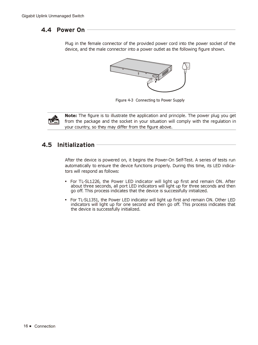
Plug in the female connector of the provided power cord into the power socket of the device, and the male connector into a power outlet as the following figure shown.
Figure 4-3 Connecting to Power Supply
Note: The figure is to illustrate the application and principle. The power plug you get
from the package and the socket in your situation will comply with the regulation in
your country, so they may differ from the figure above.
4.5 Initialization
After the device is powered on, it begins the
■■
■■
For
For
16 ![]() Connection
Connection