24+4G Gigabit Managed Switch TL-SL3452 48+4G Gigabit Managed Switch
TL-SG3109 9-port Gigabit Managed Switch TL-SL3428
Embedded Web System User Guide
FCC STATEMENT
SAFETY NOTICES
COPYRIGHT & TRADEMARKS
EC DECLARATION OF CONFORMITY EUROPE
Section 4. Configuring System Logs
TABLE OF CONTENTS
Section 3. Setting the System Time
Section 2. Defining Device Information
5.1.1.5 Defining TACACS+ Host Settings
Section 5. Configuring Device Security
Section 6. Defining IP Addresses
5.1.1.6 Defining RADIUS Server Settings
Section 10. Configuring Multicast Forwarding
Section 7. Configuring Interfaces
Section 9. Configuring the Spanning Tree Protocol
Section 11. Configuring SNMP Management
11.4 Configuring SNMP Notification Settings
Section 12. Configuring Quality of Service
Section 13. Managing System Files
11.3.1 Defining SNMP Global Parameters
Section 15. Viewing Statistics
Section 14. Performing Device Diagnostics
Glossary
Preface
Guide Overview
Intended Audience
Section 1. Getting Started
1.1 Configuring the device to use TP-Link Embedded Web Interface
1.2 Starting the TP-Link Embedded Web Interface
5. Click . The TP-Link Embedded Web Interface Home Page opens
1.3 Understanding the TP-Link Embedded Web Interface
Figure 1 Login Page
Figure 2 TP-Link Embedded Web Interface Home Page
Table 2 TP-Link Web Interface Configuration Management Buttons
1.3.2 Using the TP-Link Embedded Web Interface Management Buttons
1.3.1 Device Representation
Figure 3 Device Representation Figure 3Device Representation
1.4.1 Adding Configuration Information
1.4 Using Screen and Table Options
1.5 Deleting Configuration Information
1.4.2 Modifying Configuration Information
1. Click System General Reset. The Reset Page opens
1.6 Resetting the Device
1.7 Logging Off from the Device
Figure 7 Reset Page
Figure 10System Description Page
Section 2. Defining Device Information
2. Define the System Name, System Location and System Contact fields
Section 3. Setting the System Time
3.1 Configuring Daylight Savings Time
Figure 11 System Information Time Page
Recurring
Daylight Savings
Date - The date on which DST begins. The possible field range is
2. Define the Date, Local Time and Time Zone Offset fields
3.2.1.1 Polling for Unicast Time Information
3.2 Configuring SNTP
3.2.1 SNTP Overview
3.2.1.2 Polling for Anycast Time Information
3.2.3 Configuring SNTP Authentication
3.2.2 Defining SNTP Global Settings
Figure 12 SNTP Properties Page
The SNTP Authentication Page contains the following fields
3.2.4 Defining SNTP Servers
Figure 13 SNTP Authentication Page
2. Check the Enable SNTP Authentication checkbox
2. Click . The Add SNTP Server Page opens
3.2.5 Defining SNTP Interface Settings
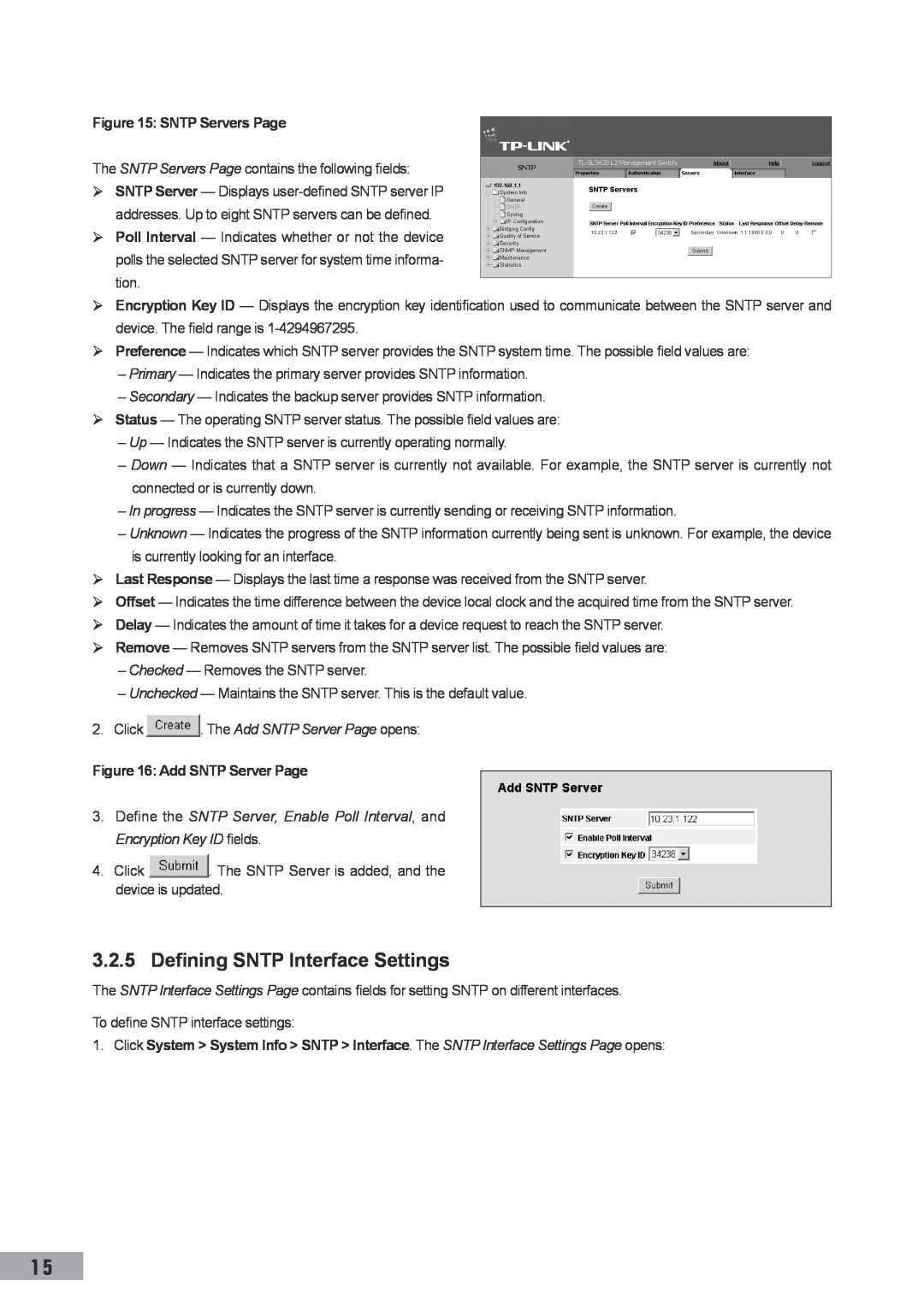
Figure 15 SNTP Servers Page
Figure 16 Add SNTP Server Page
4. Check the Receive Server Updates option
Figure 17 SNTP Interface Settings Page
The SNTP Interface Settings Page contains the following fields
2. Click . The Add SNTP Interface Page opens
Table 4 System Log Severity Levels
Section 4. Configuring System Logs
4.1 Defining General Log Properties
Severity
Figure 19 Syslog Properties Page
4.2 Viewing Memory Logs
4.3 Viewing Flash Logs
Severity
Figure 22 Syslog Servers Page
4.4 Defining System Log Servers
Figure 21 Syslog Flash Page
2. Click . The Add Syslog Server Page opens
4. Click . The Log server is defined and the device is updated
Figure 23 Add Syslog Server Page
5.1.1 Configuring Authentication Methods
Section 5. Configuring Device Security
5.1 Configuring Management Security
5.1.1.1 Defining Access Profiles
2. Click . The Add Access Profile Page opens
Figure 24 Access Profile Page
Figure 25 Add Access Profile Page
5.1.1.2 Defining Profile Rules
Figure 26 Profile Rules Page
Figure 28 Profile Rule Settings Page
5.1.1.3 Defining Authentication Profiles
2. Click . The Profile Rule Settings Page opens
Figure 29 Authentication Profiles Page
Figure 30 Add Authentication Profile Page
5.1.1.4 Mapping Authentication Profiles
2. Click . The Add Authentication Profile Page opens
2. Click . The Authentication Profile Settings Page opens
Figure 32 Authentication Mapping Page
The Authentication Mapping Page contains the following fields
2. Define the Console, Telnet, and Secure Telnet SSH fields
5.1.1.5 Defining TACACS+ Host Settings
Figure 33 TACACS+ Page
Figure 35 TACACS+ Host Settings Page
5.1.1.6 Defining RADIUS Server Settings
3. Click . The TACACS+ Host Settings Page opens
2. Click . The Add TACACS+ Host Page opens
2. Click . The Add Radius Server Page opens
Figure 36 Radius Page
Figure 37 Add Radius Server Page
1. Click . The RADIUS Server Settings Page opens
5.1.2 Configuring Passwords
5.1.2.1 Defining Local Users
Figure 38 RADIUS Server Settings Page
5.1.2.3 Defining Enable Passwords
5.2 Configuring Network Security
5.1.2.2 Defining Line Passwords
Figure 41 Line Password Page
5.2.1.2 Advanced Port-Based Authentication
5.2.2 Defining Network Authentication Properties
5.2.1.1 Port-Based Authentication
5.2.1 Network Security Overview
Figure 44 Port Authentication Page
5.2.2.1 Defining Port Authentication Properties
Figure 43 Network Security Authentication Properties Page
VLAN ID
2. Click . The Port Authentication Settings Page opens
5.2.2.2 Configuring Multiple Hosts
Figure 45 Port Authentication Settings Page
Figure 47 Multiple Host Settings Page
5.2.2.3 Defining Authentication Hosts
2. Click . The Multiple Host Settings Page opens
The Authenticated Hosts Page contains a list of authenticated users
5.2.3.1 Managing Port Security
5.2.3 Configuring Traffic Control
Figure 48 Authenticated Hosts Page
Figure 50 Port Security Settings Page
5.2.3.2 Enabling Storm Control
1. Click . The Port Security Settings Page opens
Figure 49 Port Security Page
4. Click Enable Broadcast Control, and define the Rate Threshold
Figure 52 Storm Control Settings Page
3. Select the Port Storm Control Settings
Figure 51 Storm Control Page
6.1.1 Defining IP Addresses
Section 6. Defining IP Addresses
6.1 Defining IP Addressing
Figure 53 IP Interface Page
2. Click . The IP Interface Settings Page opens
6.1.2 Defining the Default Gateway
6.1.3 Defining DHCP Addresses
Figure 55 IP Interface Settings Page
Figure 58 Add IP Interface Page
6.1.4 Defining ARP
Figure 57 DHCP Page
Figure 59 ARP Page
Default Domain Name - Specifies the user-defined DNS server name
6.2 Defining Domain Name System
6.2.1 Defining DNS Servers
3. Define the Clear ARP Table Entries parameter
4. Click . The Add DNS Server Page opens
6.2.2 Configuring Host Mapping
3. Define the Default Domain Name
Figure 62 Add DNS Server Page
Figure 64 Add DNS Host Page
3. Enter the Host Name and IP Address
7.1 Configuring Ports
Section 7. Configuring Interfaces
Figure 65 Interface Configuration Page
Figure 66 Interface Configuration Settings Page
MDI Media Dependent Interface - Use for end stations
1. Click . The LAG Membership Settings Page opens
7.2 Configuring LAGs
7.2.1 Defining LAG Members
Figure 67 LAG Membership Page
The LAG Membership Settings Page contains the following fields
7.2.2 Configuring LACP
Figure 68 LAG Membership Settings Page
2. Click . The LACP Parameters Settings Page opens
Figure 70 LACP Parameters Settings Page
7.3 Configuring VLANs
7.3.1 Defining VLAN Properties
3. Define the Port Priority and LACP Timeout settings
Figure 71 VLAN Member Properties Page
7.3.2 Defining VLAN Membership
2. Modify the VLAN Name and Disable Authentication fields
The VLAN Member Properties Page contains the following fields
The VLAN Interface Settings Page contains the following fields
7.3.3 Defining VLAN Interface Settings
Figure 75 VLAN Interface Settings Page
Figure 74 VLAN Member Membership Page
1. Click . The VLAN / LAG Interface Settings Page opens
7.3.4 Configuring GARP
7.3.4.1 Defining GARP
Figure 76 VLAN / LAG Interface Settings Page
Figure 78 GARP Parameters Settings Page
7.3.5 Defining GVRP
Figure 77 GARP Parameters Page
Figure 80 GVRP Parameters Settings Page
Figure 79 GVRP Parameters Page
Section 8. Defining the Forwarding Database
8.1 Configuring Static Addresses
Figure 81 Forwarding Database Static Addresses Page
Figure 82 Add Forwarding Database Page
8.2 Configuring Dynamic Forwarding Addresses
2. Click . The Add Forwarding Database Page opens
Figure 83 Dynamic Addresses Page
2. Select the Interface, the MAC Address, and the VLAN ID
3. Select an Address Table Sort Key
Section 9. Configuring the Spanning Tree Protocol
9.1 Configuring the Classic STP
9.1.1 Defining STP Properties
1. Click System Bridging Info Spanning Tree STP
9.1.2 Defining STP Interface Settings
2. Complete the Spanning Tree State and Bridge Settings fields
1. Click . The STP Interface Settings Page opens
Figure 85 STP Interface Settings Page
The STP Interface Settings Page contains the following fields
Figure 86 STP Interface Settings Page
9.2 Configuring the Rapid STP
Figure 87 RSTP Page
2. Click . The RSTP Settings Page opens
9.3 Configuring the Multiple STP
9.3.1 Defining MSTP Properties
Figure 88 RSTP Settings Page
The MSTP Instance Settings Page page contains the following fields
9.3.2 Configuring MSTP Instances
Figure 90 MSTP Instance Settings Page
Figure 89 MSTP Properties Page
MSTP VLAN Instance Configuration Page opens
9.3.3 Configuring MSTP VLAN Instances
9.3.4 Configuring MSTP Interface Settings
Figure 91 MSTP VLAN Instance Configuration Page
Figure 93 MSTP Interface Settings Page
3. Modify the Port Priority and Path Cost
10.1 Configuring Multicast Forwarding
Section 10. Configuring Multicast Forwarding
Figure 94 IGMP Snooping Page
1. Click . The Multicast Global Parameters Settings Page opens
10.2 Defining Multicast Bridging Groups
2. Click the Enable IGMP Snooping Status checkbox
Figure 95 Multicast Global Parameters Settings Page
Figure 98 Multicast Group Settings Page
Table 5 IGMP Port/LAG Members Table Control Settings
2. Click . The Multicast Group Settings Page opens
Port Control
The Multicast Forward All Page contains the following fields
10.3 Defining Multicast Forward All Parameters
Figure 99 Multicast Forward All Page
Port Control
11.3 Defining SNMP Security
11.1 SNMP v1 and v2c
11.2 SNMP
Section 11. Configuring SNMP Management
2. Define the Local Engine ID and Use Default fields
11.3.1 Defining SNMP Global Parameters
11.3.2 Defining SNMP Views
Figure 100 SNMP Security Global Parameters Page
Figure 102 Add SNMP View Page
11.3.3 Defining SNMP Group Profiles
2. Click . The Add SNMP View Page opens
Figure 103 SNMP Security Group Profile Page
Figure 105 SNMP Group Profile Settings Page
11.3.4 Defining SNMP Group Members
2. Click . The SNMP Group Profile Settings Page opens
2. Click . The Add SNMP Group Profile Page opens
Figure 108 SNMP Group Membership Settings Page
Authentication Method - Defines the SNMP authentication method
2. Click . The SNMP Group Membership Settings Page opens
Figure 107 Add SNMP Group Membership Page
11.3.5.2 SNMP Communities Advanced Table
11.3.5 Defining SNMP Communities
11.3.5.1 SNMP Communities Basic Table
Figure 109 SNMP Security Communities Page
11.4.2 Defining Notification Filters
11.4 Configuring SNMP Notification Settings
11.4.1 Defining SNMP Notification Properties
Figure 111 SNMP Community Settings Page
The SNMP Notification FiIter Page contains the following fields
11.4.3 Defining Notification Receivers
Figure 113 SNMP Notification FiIter Page
2. Click . The Add SNMP Notification Filter Page opens
Figure 115 SNMP Notification Receiver Page
11.4.3.1 SNMPv1,2c Notification Recipient
11.4.3.2 SNMPv3 Notification Recipient
The SNMP Notification Receiver Page c is divided into the
UPD Port, Filter Name, TImeout, and Retries fields
2. Click . The SNMP Notification Receiver Settings Page opens
Figure 117 SNMP Notification Receiver Settings Page
2. Click . The Add SNMP Notification Receiver Page opens
12.1 Quality of Service Overview
Section 12. Configuring Quality of Service
12.1.1 Mapping to Queues
Table 8 DSCP Default Mapping Table
12.1.2 QoS Modes
Table 7 VPT Default Mapping Table
VPT Value
12.1.2.1 Basic QoS Mode
12.2 Enabling Quality of Service
12.2.1 Enabling Quality of Service
12.1.2.2 Advanced QoS Mode
Figure 118 CoS Settings Page
12.2.2 Defining Queues
Figure 119 QoS Interface Settings Page
12.3.2 Mapping QoS Values to Queues
12.3 Mapping Queues
12.3.1 Mapping CoS Values to Queues
Figure 120 QoS Queue Settings Page
Figure 122 DSCP to Queue Page
13.1.1 Download Type
Section 13. Managing System Files
13.1 Downloading System Files
Figure 123 File Download Page
13.1.2 Firmware Download
13.1.3 Configuration Download
13.2 Uploading System Files
13.2.1 Upload Type
13.4 Copying System Files
13.2.3 Configuration Upload
13.3 Activating Image Files
13.2.2 Software Image Upload
2. Select Restore Configuration Factory Defaults
2. Select Copy Configuration
Figure 126 Copy Files Page
Figure 127 Port Mirroring Page
Section 14. Performing Device Diagnostics
14.1 Configuring Port Mirroring
Figure 128 Add Port Mirroring Page
Figure 129 Port Mirroring Settings Page
14.2 Viewing Integrated Cable Tests
1. Click . The Port Mirroring Settings Page opens
Figure 130 Copper Cable Page
Figure 131 Optical Transceivers Page
14.3 Viewing Optical Transceivers
The Optical Transceivers Page contains the following fields
15.1.1 Viewing Device Interface Statistics
Section 15. Viewing Statistics
15.1 Viewing Interface Statistics
Receive Statistics
1. Open the Interface Statistics Page
15.1.2 Viewing Etherlike Statistics
Transmit Statistics
Figure 133 Etherlike Statistics Page
1. Open the Etherlike Statistics Page
15.1.3 Viewing GVRP Statistics
Figure 134 GVRP Statistics Page
1. Open the GVRP Statistics Page
15.2 Managing RMON Statistics
15.1.4 Viewing EAP Statistics
Figure 135 EAP Statistics Page
15.2.1 Viewing RMON Statistics
Figure 136 RMON Statistics Page
1. Open the RMON Statistics Page
15.2.2 Configuring RMON History
15.2.2.1 Defining RMON History Control
Figure 137 RMON History Control Page
1. Open the RMON History Control Page
15.2.2.2 Viewing the RMON History Table
Figure 138 Add History Entry User Page
2. Click . The Edit Local History Entry User Page opens
Figure 141 RMON Events Control Page
15.2.3 Configuring RMON Events
15.2.3.1 Defining RMON Events Control
The RMON Events Control Page contains the following fields
1. Click System Statistics RMON Alarm. The RMON Alarm Page opens
15.2.4 Defining RMON Alarms
15.2.3.2 Viewing the RMON Events Logs
Figure 145 RMON Alarm Page
Figure 146 Add RMON Alarm User Page
2. Click . The Add RMON Alarm User Page opens
1. Click . The Edit RMON Alarm User Page opens
Figure 147 Edit RMON Alarm User Page
2. Modify the fields
Access Profile
Glossary
Access Mode
Authentication Profile
Class of Service
Boot Version
BootP
Term
Client
Term
Definition
Collision
Ethernet
Term
Definition
FIFO
ICMP
Term
Definition
IDRP
Definition
authenticates the origin of the communication
Term
limited geographical area
Node
Term
Definition
OSPF
Running Configuration
RJ-11 Connector
RJ-45 Connector
Startup Configuration
Subnet Mask
Term
Definition
TCP/IP
E-mail support@tp-link.com

 . The Add SNTP Server Page opens: