Embedded Web System User Guide
Copyright & Trademarks FCC Statement
Table of Contents
Configuring Authentication Methods
Defining Access Profiles
Defining Authentication Profiles
Mapping Authentication Profiles
Configuring Garp
Configuring the Classic STP Defining STP Properties
Configuring Multicast Forwarding
Defining Gvrp
Basic QoS Mode
Advanced QoS Mode
Configuration Download
Configuration Upload
Viewing Statistics
Glossary
Preface
Guide Overview
Intended Audience
Getting Started
Starting the TP-Link Embedded Web Interface
Interface Components
Understanding the TP-Link Embedded Web Interface
Click . The TP-Link Embedded Web Interface Home Page opens
Using the TP-Link Embedded Web Interface Management Buttons
TP-Link Web Interface Configuration Management Buttons
Device Representation
TP-Link Web Interface Information Buttons
Using Screen and Table Options
Deleting Configuration Information
Adding Configuration Information
Modifying Configuration Information
Resetting the Device
Click System General Reset. The Reset Page opens
Logging Off from the Device
Click . a confirmation message is displayed
Defining Device Information
System Description
Setting the System Time
Configuring Daylight Savings Time
System Information Time
Define the Date, Local Time and Time Zone Offset fields
Daylight Savings
Recurring
Configuring Sntp
Sntp Overview
Polling for Unicast Time Information
Polling for Anycast Time Information
Sntp Properties Page contains the following fields
Defining Sntp Global Settings
Configuring Sntp Authentication
To configure Sntp authentication
Sntp Authentication Page contains the following fields
Check the Enable Sntp Authentication checkbox
Click . The Add Sntp Authentication Page opens
Defining Sntp Interface Settings
Click . The Sntp Server is added, and the device is updated
Sntp Servers Page contains the following fields
Click . The Add Sntp Server Page opens
Sntp Interface Settings Page contains the following fields
Check the Receive Server Updates option
Click . The Add Sntp Interface Page opens
Select the Interface
Configuring System Logs
Defining General Log Properties
Following table lists the log severity levels
System Log Severity Levels
Severity
Viewing Memory Logs
Viewing Flash Logs
Click . The Add Syslog Server Page opens
Defining System Log Servers
To view Flash memory logs
Click . The Log server is defined and the device is updated
Add Syslog Server
Configuring Device Security
Configuring Management Security
Configuring Authentication Methods
Defining Access Profiles
Access Profile
Click . The Add Access Profile Page opens
Defining Profile Rules
Profile Rules
Authentication Profiles Page provides the following
Defining Authentication Profiles
Click . The Profile Rule Settings Page opens
Mapping Authentication Profiles
Click . The Add Authentication Profile Page opens
Click . The Authentication Profile Settings Page opens
Define the Profile Method and enter the Profile Name fields
Authentication Mapping
Authentication Mapping Page contains the following fields
Defining TACACS+ Host Settings
To define TACACS+ authentication settings
Session is permitted
Define the Console, Telnet, and Secure Telnet SSH fields
Defining Radius Server Settings
Click . The TACACS+ Host Settings Page opens
Click . The Add TACACS+ Host Page opens
Select TACACS+ server entry
Radius
Click . The Add Radius Server Page opens
Configuring Passwords
Click . The Radius Server Settings Page opens
Defining Local Users
Click . The Add Local User Page opens
Configuring Network Security
Defining Line Passwords
Defining Enable Passwords
Line Password Page contains the following fields
Defining Network Authentication Properties
Port-Based Authentication
Advanced Port-Based Authentication
Network Security Overview
Defining Port Authentication Properties
Port Authentication Page contains the following fields
Configuring Multiple Hosts
Click . The Port Authentication Settings Page opens
To define authenticated users
Defining Authentication Hosts
Click . The Multiple Host Settings Page opens
Configuring Traffic Control
Managing Port Security
Click . The Port Security Settings Page opens
Enabling Storm Control
Storm Control
Cast B, cast M tbd Cast M, cast tbd Cast tbd
Defining IP Addresses
Defining IP Addressing
Defining IP Addresses
Click . The Add IP Interface Page opens
Defining the Default Gateway
Click . The IP Interface Settings Page opens
Enter the name of the User Defined Default Gateway
Defining Dhcp Addresses
ARP Page contains the following fields
Defining ARP
To define ARP
Defining Domain Name System
Defining DNS Servers
DNS Server Page contains the following fields
Type Displays the IP address type. The possible
Configuring Host Mapping
Host Mapping Page contains the following fields
Add DNS Host
Enter the Host Name and IP Address
Configuring Interfaces
Configuring Ports
Interface Configuration Settings
Click . The parameters are saved, and the device is updated
Configuring LAGs
Click . The LAG Membership Settings Page opens
Defining LAG Members
To define LAG members
Configuring Lacp
LAG Membership Settings Page contains the following fields
Click . The Lacp Parameters Settings Page opens
Lacp Parameters Page contains the following fields
Defining Vlan Properties
Configuring VLANs
Define the Port Priority and Lacp Timeout settings
Modify the Vlan Name and Disable Authentication fields
Defining Vlan Membership
Vlan Member Properties Page contains the following fields
Click . The Vlan properties are saved
Defining Vlan Interface Settings
Vlan Interface Settings Page contains the following fields
To define Vlan membership
Vlan Member Membership Page contains the following fields
Defining Garp
Configuring Garp
Click . The Vlan / LAG Interface Settings Page opens
To define Gvrp on the device
Defining Gvrp
Garp Parameters Page contains the following fields
Gvrp Parameters
Configuring Static Addresses
Forwarding Database Static Addresses
Configuring Dynamic Forwarding Addresses
Click . The Add Forwarding Database Page opens
To define the dynamic forwarding addresses
Clear Table Clears the Current Address Table
Select the Interface, the MAC Address, and the Vlan ID
Select an Address Table Sort Key
Configuring the Classic STP
Defining STP Properties
Click System Bridging Info Spanning Tree STP
Properties. The STP Properties Page opens
Defining STP Interface Settings
Complete the Spanning Tree State and Bridge Settings fields
Click the STP enable checkbox Define the fields
STP Interface Settings Page contains the following fields
Click . The STP Interface Settings Page opens
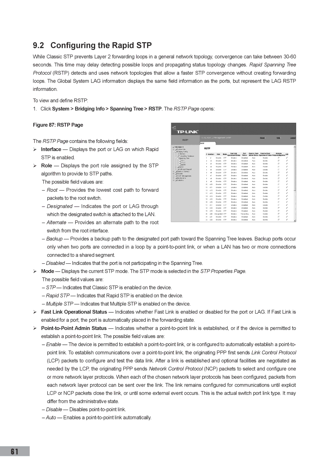
Configuring the Rapid STP
Rstp
Defining Mstp Properties
Configuring the Multiple STP
Click . The Rstp Settings Page opens
Define the Region Name, Revision and Max Hops fields
Configuring Mstp Instances
Click . The device information is updated
Configuring Mstp Vlan Instances
Configuring Mstp Interface Settings
Mstp Vlan Instance Configuration Page opens
Mstp Interface Settings Page contains the following fields
Mstp Interface Settings
Modify the Port Priority and Path Cost
Configuring Multicast Forwarding
Igmp Snooping Page contains the following fields
Click the Enable Igmp Snooping Status checkbox
Click . The Multicast Global Parameters Settings Page opens
Defining Multicast Bridging Groups
To define multicast groups
Igmp Port/LAG Members Table Control Settings
Click . The Multicast Group Settings Page opens
Multicast group statically in the Current Row
Join a Multicast group
Port is not attached to a Multicast router or switch
Defining Multicast Forward All Parameters
Multicast Forward All Page contains the following fields
Forbidden
Defining Snmp Security
Snmp v1 and v2c
Snmp
Define the Local Engine ID and Use Default fields
Defining Snmp Global Parameters
Defining Snmp Views
Snmp Security Views Page contains the following fields
Defining Snmp Group Profiles
Click . The Add Snmp View Page opens
Click . The Add Snmp Group Profile Page opens
Click . The Snmp Group Profile Settings Page opens
Defining Snmp Group Members
Click . The Snmp Group Membership Settings Page opens
Addition to the fields in the Snmp Security Group
Membership Page, The Add Snmp Group Membership
Contains the following fields
Defining Snmp Communities
Snmp Communities Basic Table
Snmp Communities Advanced Table
Snmp Security Communities Page is divided into
Configuring Snmp Notification Settings
Device is updated To modify Snmp Group Membership settings
Defining Snmp Notification Properties
Defining Notification Filters
Click . The Add Snmp Notification Filter Page opens
Defining Notification Receivers
Snmp Notification FiIter Page contains the following fields
Snmp Notification Receiver Page c is divided into
SNMPv1,2c Notification Recipient
SNMPv3 Notification Recipient
Click . The Snmp Notification Receiver Settings Page opens
Click . The Add Snmp Notification Receiver Page opens
Mapping to Queues
Configuring Quality of Service
Quality of Service Overview
Following table contains the VPT to Queue default settings
VPT Default Mapping Table
Dscp Default Mapping Table
QoS Modes
Enabling Quality of Service
Enabling Quality of Service
Basic QoS Mode
Advanced QoS Mode
CoS Settings
Defining Queues
Mapping Queues
Mapping CoS Values to Queues
Mapping QoS Values to Queues
Scheduling
Dscp to Queue
Managing System Files
Downloading System Files
Download Type
To download system files
Configuration Download
Uploading System Files
Firmware Download
Upload Type
Configuration Upload
Activating Image Files
Copying System Files
Software Image Upload
Select Copy Configuration
Select Restore Configuration Factory Defaults
Performing Device Diagnostics
Configuring Port Mirroring
To modify port mirroring settings
Click . The Port Mirroring Settings Page opens
Viewing Integrated Cable Tests
Click the Remove checkbox for selected item, and click
Viewing Optical Transceivers
Optical Transceivers Page contains the following fields
Viewing Statistics
Viewing Interface Statistics
Viewing Device Interface Statistics
Interface Statistics Page contains the following fields
Viewing Etherlike Statistics
Open the Interface Statistics
Click . The interface statistics counters are cleared
Etherlike Statistics Page contains the following fields
Viewing Gvrp Statistics
Open the Etherlike Statistics
Managing Rmon Statistics
Viewing EAP Statistics
Open the Gvrp Statistics
Click . The Gvrp interface statistics counters are cleared
Rmon Statistics Page contains the following fields
Configuring Rmon History Defining Rmon Alarms
Viewing Rmon Statistics
Configuring Rmon History
Defining Rmon History Control
Open the Rmon Statistics
Rmon History Control Page contains the following fields
Viewing the Rmon History Table
Rmon History Table Page contains the following fields
Configuring Rmon Events
Defining Rmon Events Control
Rmon Events Control Page contains the following fields
Click . The Add Rmon Event User Page opens
Click System Statistics Rmon Events.
Defining Rmon Alarms
Viewing the Rmon Events Logs
Click . The Edit Rmon Alarm User Page opens
Click . The Add Rmon Alarm User Page opens
To modify an Rmon alarm user
103
Glossary
Boot Version
BootP
Class of Service
Backplane
Duplex Mode
Client
Collision
Combo Port
Ethernet
Flapping
Flow Control
Fragment
Ieee 802.1d
Ieee 802.1p
EEE 802.1q
Image File
Authenticates the origin of the communication
Limited geographical area
Process
Processing, as there is more information to process
Node
Packet
Policing
Port
RJ-11 Connector
RJ-45 Connector
Running Configuration
Stand-alone Mode
Subnet Mask
Telnet
Trap
Trunking
71035590