Application Considerations

The following is the procedure to use when selecting a fan for elevations and temperatures other than standard:

1

Determine the air density from Figure A-3.

2

Divide static pressure at the non- standard condition by the air density ratio.

3

Use the actual cfm and corrected static pressure to determine rpm and bhp from the fan performance tables.

4

The rpm is correct as selected.

5

The bhp must be multiplied by the air density ratio determined in step one to get the actual operating bhp.

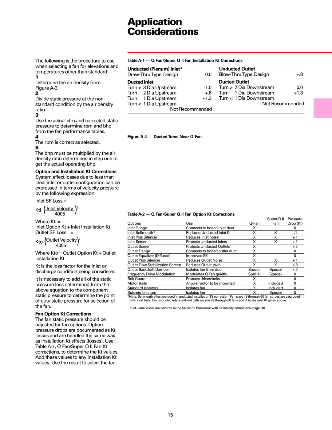
Option and Installation Kt Corrections System effect losses due to less than ideal inlet or outlet configuration can be expressed in terms of velocity pressure by the following expression:

Inlet SP Loss =

Kti (Inlet4005Velocity )2

Where Kti =

Inlet Option Kt + Inlet Installation Kt

Outlet SP Loss =

Kto (Outlet Velocity)2

4005

Where Kto = Outlet Option Kt + Outlet Installation Kt

Kt is the loss factor for the inlet or discharge condition being considered.

It is necessary to add all of the static pressure loss determined from the above equation to the component static pressure to determine the point of duty static pressure for selection of the fan.

Fan Option Kt Corrections

The fan static pressure should be adjusted for fan options. Option pressure drops are documented as Kt losses and are handled the same way as installation Kt effects (losses). Use Table A-1, Q Fan/Super Q II Fan Kt corrections, to determine the Kt values. Add these values to any installation Kt values. Use the result to select the fan.

Table A-1 — Q Fan/Super Q II Fan Installation Kt Corrections

Unducted (Plenum) Inlet*


Unducted Outlet


Draw-Thru Type Design

0.0

Blow-Thru Type Design

+.8

Ducted Inlet


Ducted Outlet


Turn > 3 Dia Upstream

-1.0

Turn > 2 Dia Downstream

0.0

Turn

2 Dia Upstream

+.8

Turn 1 Dia Downstream

+1.3

Turn

1 Dia Upstream

+1.3

Turn < 1 Dia Downstream


Turn < 1 Dia Upstream


Not Recommended


Not Recommended


Figure A-4 — Ducted Turns Near Q Fan

Table A-2 — Q Fan/Super Q II Fan Option Kt Corrections


Super Q II

Pressure

Options

Use

Q-Fan

Fan

Drop (Kt)

Inlet Flange

Connects to bolted inlet duct

X


0

Inlet Bellmouth*

Reduces Unducted Inlet Kt

X

X

-.1

Inlet Plus Silencer

Reduces inlet noise

X

X

+.1

Inlet Screen

Protects Unducted Inlets

X

X

+.1

Outlet Screen

Protects Unducted Outlets

X


+.5

Outlet Flange

Connects to bolted outlet duct

X


0

Outlet Equalizer (Diffuser)

Improves SE

X


0

Outlet Plus Silencer

Reduces Outlet Noise

X

X

+.1

Outlet Flow Stabilization Screen

Reduces Outlet swirl

X

X

+.8

Outlet Backdraft Damper

Isolates fan from duct

Special

Special

+.5

Frequency Drive Modulation

Modulates Q Fan quietly

Special

Special

0

Belt Guard

Protects drives/belts

X


0

Motor Rails

Allows motor to be mounted

X

Included

0

Standard Isolators

Isolates fan

X

Included

0

Seismic Isolators

Isolates fan

X

Special

0

*Note: Bellmouth effect included in unducted installation Kt correction. Fan sizes 49 through 60 fan curves are cataloged with inlet bells. For unducted inlets without bells on size 49 through 60 fans add .1 to the inlet Kt given above.

Inlet vane losses are covered in the Selection Procedure with air density corrections (page 20).

15

Page 15
Image 15
Trane manual Fan Option Kt Corrections, Unducted Plenum Inlet Unducted Outlet, Ducted Inlet Ducted Outlet

Fan specifications

Trane is a well-known name in the heating, ventilation, and air conditioning (HVAC) industry, and one of their standout products is the Trane Fan. Designed to provide efficient and effective airflow, the Trane Fan is a versatile solution suited for both residential and commercial applications.

One of the main features of the Trane Fan is its Energy Efficiency. With increasing energy costs, having a fan that operates efficiently is crucial. Trane fans are designed with advanced motor technology that enhances performance while reducing energy consumption. This not only helps lower utility bills but also contributes to a more sustainable environment.

The Variable Speed Technology is another notable characteristic. Trane fans come equipped with variable speed motors that adjust the airflow according to the specific needs of a space. This adaptability means that the fan can run at lower speeds, providing quiet operation while maintaining comfort levels, and ramping up power when needed for more intense cooling or ventilation.

Durability and robustness are core attributes of Trane fans. Constructed from high-quality materials, these fans are built to withstand harsh conditions and continue to function optimally over time. This longevity is essential for commercial settings where reliability is paramount.

Additionally, Trane delivers innovative sound-reduction technologies within their fan designs. Special engineering ensures that these units operate quietly, making them ideal for environments such as offices, schools, and homes where noise can be a distraction.

Another significant aspect is Smart Technology Integration. Trane fans are compatible with various smart home systems, allowing users to control their systems remotely. This feature enhances convenience, enabling homeowners and facility managers to monitor and adjust air quality effortlessly.

In terms of ease of installation, Trane Fans are designed with user-friendly features that facilitate quicker setup and less hassle. Their modular designs allow for flexibility in installation across various applications.

In summary, the Trane Fan stands out due to its energy efficiency, variable speed technology, durability, sound-reduction capabilities, smart technology integration, and ease of installation. These characteristics make Trane fans a reliable choice for enhancing indoor air quality across diverse environments.