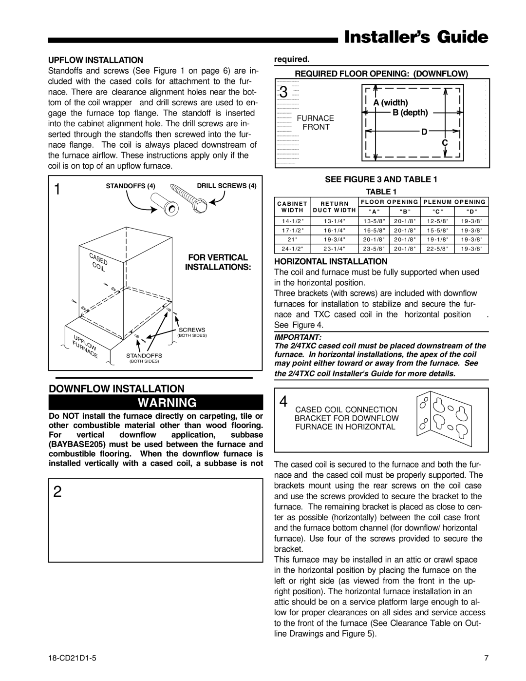
UPFLOW INSTALLATION
Standoffs and screws (See Figure 1 on page 6) are in- cluded with the cased coils for attachment to the fur- nace. There are clearance alignment holes near the bot- tom of the coil wrapper and drill screws are used to en- gage the furnace top flange. The standoff is inserted into the cabinet alignment hole. The drill screws are in- serted through the standoffs then screwed into the fur- nace flange. The coil is always placed downstream of the furnace airflow. These instructions apply only if the coil is on top of an upflow furnace.
1 | STANDOFFS (4) | DRILL SCREWS (4) |
|
CASED | FOR VERTICAL |
COIL | INSTALLATIONS: |
| SCREWS |
UPFLOW | (BOTH SIDES) |
| |
FURNACE | STANDOFFS |
| (BOTH SIDES) |
DOWNFLOW INSTALLATION
▲! WARNING
Do NOT install the furnace directly on carpeting, tile or other combustible material other than wood flooring. For vertical downflow application, subbase (BAYBASE205) must be used between the furnace and combustible flooring. When the downflow furnace is installed vertically with a cased coil, a subbase is not
2
Installer’s Guide
required.
REQUIRED FLOOR OPENING: (DOWNFLOW)
3 | A (width) |
| |
FURNACE | B (depth) |
| |
FRONT | D |
| |
| C |
SEE FIGURE 3 AND TABLE 1
TABLE 1
C A B IN E T | R E T U R N | FLO O R O P E N IN G | P LE N U M O P E N IN G | |||
W ID T H | D U C T W ID TH | "A " |
| "B " | "C " | "D " |
|
|
|
|
|
|
|
1 | 1 3 | 1 | 2 | 1 2 | 1 9 | |
1 7 | 1 6 | 1 6 | 2 | 1 5 | 1 9 | |
|
|
|
|
|
|
|
2 1 " | 1 9 | 0 | 2 | 1 9 | 1 9 | |
|
|
|
|
|
|
|
2 | 2 3 | 2 | 2 2 | 1 9 | ||
|
|
|
|
|
|
|
HORIZONTAL INSTALLATION
The coil and furnace must be fully supported when used in the horizontal position.
Three brackets (with screws) are included with downflow furnaces for installation to stabilize and secure the fur- nace and TXC cased coil in the horizontal position. See Figure .
IMPORTANT:
The 2/4TXC cased coil must be placed downstream of the furnace. In horizontal installations, the apex of the coil may point either toward or away from the furnace. See
the 2/4TXC coil Installer's Guide for more details.
CASED COIL CONNECTION
BRACKET FOR DOWNFLOW
FURNACE IN HORIZONTAL
The cased coil is secured to the furnace and both the fur- nace and the cased coil must be properly supported. The brackets mount using the rear screws on the coil case and use the screws provided to secure the bracket to the furnace. The remaining bracket is placed as close to cen- ter as possible (horizontally) between the coil case front and the furnace bottom channel (for downflow/ horizontal furnace). Use four of the screws provided to secure the bracket.
This furnace may be installed in an attic or crawl space in the horizontal position by placing the furnace on the left or right side (as viewed from the front in the up- right position). The horizontal furnace installation in an attic should be on a service platform large enough to al- low for proper clearances on all sides and service access to the front of the furnace (See Clearance Table on Out- line Drawings and Figure ).
7 |