UH-SVX01A-EN specifications
The Trane UH-SVX01A-EN is an advanced unit ventilator designed to provide efficient and reliable heating, cooling, and ventilation in various commercial and educational applications. This unit is particularly engineered for use in schools, offices, and healthcare facilities, ensuring optimal indoor air quality while maintaining energy efficiency.One of the main features of the UH-SVX01A-EN is its innovative design that incorporates cutting-edge technologies for enhanced performance. The unit is equipped with a high-efficiency fan and motor system that operates quietly while delivering consistent airflow. This ensures a comfortable environment for occupants without the disruptive noise common in traditional ventilation systems.
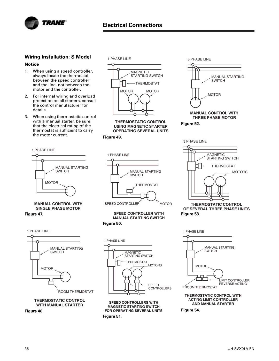
Another standout characteristic of the UH-SVX01A-EN is its versatility. It offers multiple configuration options, allowing it to be tailored to meet specific building requirements and occupant needs. The unit can be integrated with various control systems, including advanced building management systems, which provide precise temperature control and enhance energy savings.
The use of variable air volume technology allows the UH-SVX01A-EN to adjust airflow rates based on real-time occupancy and environmental conditions. This intelligent airflow management not only improves comfort but also significantly reduces energy consumption, aligning with sustainable building practices.
Additionally, Trane has incorporated a range of filtration options within the unit, which contribute to improved indoor air quality by capturing dust, allergens, and other airborne particulates. This makes the UH-SVX01A-EN an ideal choice for settings where air purity is paramount, such as healthcare environments.
Maintenance of the UH-SVX01A-EN is also user-friendly, with easy access to key components for servicing and inspections. Trane's commitment to reliability and efficiency is manifested in the durable materials and construction of this unit, ensuring longevity and lower lifetime operational costs.
In summary, the Trane UH-SVX01A-EN combines advanced technology, versatile configurations, and a focus on energy efficiency and indoor air quality. This unit ventilator is designed to meet the demands of modern buildings while supporting environmental sustainability initiatives. With its robust features and flexible integration options, the UH-SVX01A-EN stands out as a reliable solution for any commercial heating, cooling, and ventilation needs.

