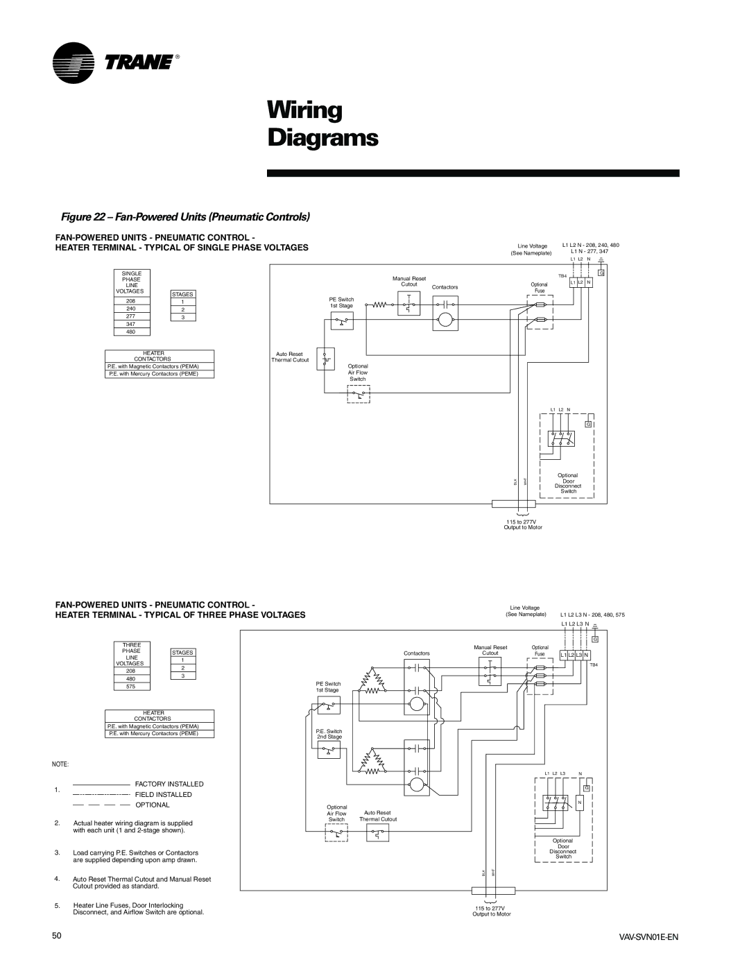
VAV-SVN01E-EN, Trane specifications
The Trane VAV-SVN01E-EN is an advanced variable air volume (VAV) system designed to optimize indoor air quality and energy efficiency in commercial buildings. This system is part of Trane’s commitment to offering reliable, innovative HVAC solutions that meet the demands of modern architectural designs and energy standards.One of the main features of the VAV-SVN01E-EN is its ability to control air flow based on occupancy and environmental conditions. This ensures that energy is used efficiently, as airflow can be adjusted to match real-time needs, rather than operating at a constant rate. The integration of intelligent sensors allows the system to adapt dynamically, leading to both reduced energy consumption and improved comfort for building occupants.
The technology behind the VAV-SVN01E-EN includes advanced digital controls and integration capabilities. These controls enable the system to communicate seamlessly with building management systems (BMS), allowing for centralized monitoring and management. This interconnected approach not only enhances operational efficiency but also enables predictive maintenance, helping facility managers identify and address potential issues before they become problematic.
Energy efficiency is further enhanced through the use of VAV technology, which reduces the amount of conditioned air delivered when spaces are unoccupied or when less cooling or heating is required. This tailored approach contributes to lower energy costs and supports sustainability initiatives by decreasing the overall carbon footprint of the building.
Key characteristics of the Trane VAV-SVN01E-EN include its compact design, which facilitates easy installation in existing spaces without significant modifications. The unit is also designed for low sound levels, ensuring that it operates quietly, contributing to a more pleasant indoor environment. Moreover, the VAV system is engineered to be reliable and durable, with rigorous testing and high-quality components ensuring long-term performance.
In summary, the Trane VAV-SVN01E-EN stands out in the field of HVAC solutions, bringing together advanced technology, energy efficiency, and user comfort. Its features are tailored for modern building requirements, making it a preferred choice for facility managers aiming to enhance indoor air quality while reducing operational costs.

